
A high-efficiency settling device

A settling device and high-efficiency technology, which can be used in settling tanks, separation methods, filtration and separation, etc., can solve the problems of slow concentration and settling speed, bulky volume, and increased construction costs, so as to speed up the concentration speed, improve the concentration efficiency, and reduce the difficulty of construction. Effect

Active Publication Date: 2018-11-23
国家电投集团山西铝业有限公司
View PDF11 Cites 0 Cited by
  • Summary
  • Abstract
  • Description
  • Claims
  • Application Information

AI Technical Summary

Problems solved by technology

The thickener is not suitable for thickening materials larger than 0.3 mm, otherwise it will be easily silted; the concentration of the underflow pulp concentrated by the thickener is low; and if the machine breaks down, the continuity of production cannot be guaranteed; uniform
Another commonly used thickening and settling device in the prior art is the deep cone settling tank. Due to the high height of the deep cone settling tank, the concentrated underflow pulp has a high concentration, but its disadvantage is that the concentration and settling speed is slow; and the cost is high. The deep cone settling tank is bulky and has a large vertical height. The outriggers need to bear a very large pressure. This requires that the support must be firm, so the construction cost increases. At the same time, it also makes the construction difficult.

Method used


Image

  • A high-efficiency settling device
  • A high-efficiency settling device
  • A high-efficiency settling device

Examples


Embodiment 1

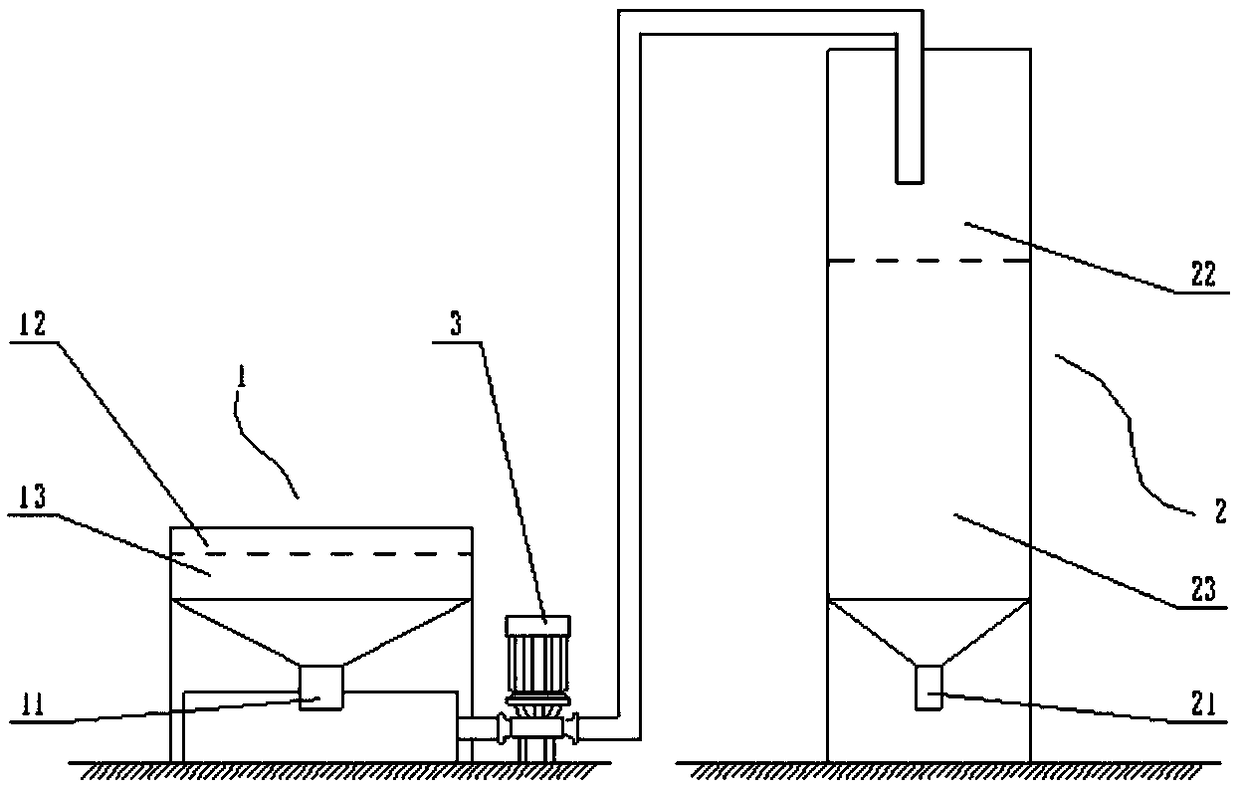
[0036] The technical scheme adopted in this embodiment is as follows: figure 1 As shown, it includes the primary settling tank 1 and the secondary settling tank 2 connected in series.

[0037] Both the primary settling tank 1 and the secondary settling tank 2 are cylindrical.

[0038] The column height of the primary settling tank 1 is H 1 , the cylinder diameter of the primary settling tank 1 is D 1 , the column height of the secondary settling tank 2 is H 2 , the cylinder diameter of the secondary settling tank 2 is D 2 .

[0039] Height H of primary settling tank 1 1 ≤5.0m, and the height H of the primary settling tank 1 1 and the diameter D of the primary settling tank 1 1 Ratio H 1 / D 1 ≤0.3;

[0040] The height H of the secondary settling tank 2 2 ≥5.0m, and the height H of the secondary settling tank 2 2 and the diameter D of the secondary settling tank 2 2 Ratio H 2 / D 2 ≥5;

[0041] Diameter D of primary settling tank 1 1 and the diameter D of the sec...

Embodiment 2

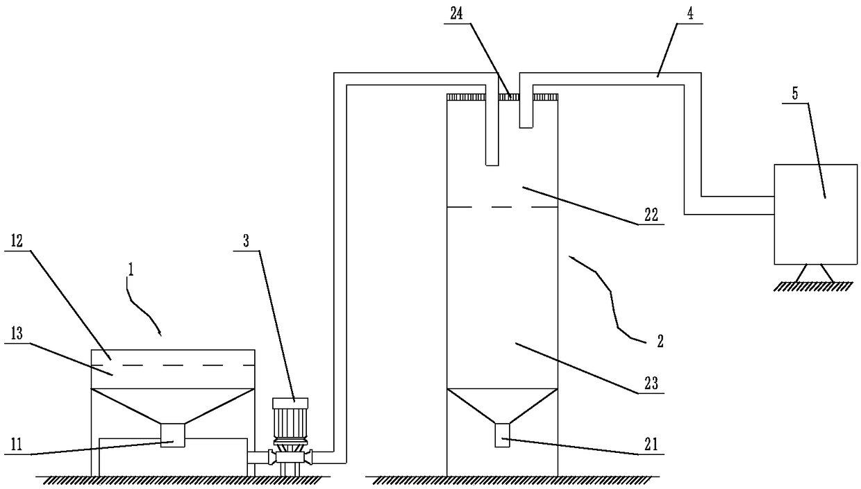
[0046] The technical scheme adopted in this embodiment is as follows: figure 2 As shown, it includes the primary settling tank 1 and the secondary settling tank 2 connected in series.

[0047] In the present embodiment, the bottom surface of the primary settling tank 1 is a conical surface, and the bottom surface of the primary settling tank 1 is provided with a primary underflow slurry outlet 11. On the upper surface of the conical surface, the gravity of the solid particles is decomposed into The downward force and the force perpendicular to the cone surface, the reaction force formed by the force perpendicular to the cone surface can be used for further concentration and settlement between solid particles, and the force along the cone surface can make the solid particles along the cone while concentrating and settling. The surface slowly slides down and flows out from the first-level underflow slurry outlet 11.

[0048] In other embodiments, the bottom surface of the prim...

Embodiment 3

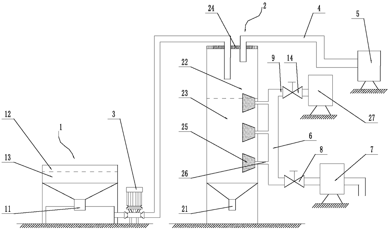
[0058] See image 3 As shown, the difference between embodiment 3 and embodiment 2 is that at least one microporous filter plate 25 is also arranged in the secondary settling tank 2, and the microporous filter plate 25 is all vertically fixed on the inner wall of the secondary settling tank 2 , the liquid outlet pipe 26 of the microporous filter plate 25 passes through the tank wall of the secondary settling tank 2, and the liquid outlet pipe of the microporous filter plate 25 is tightly fitted with the tank wall of the secondary settling tank 2 to prevent the slurry from leaking out , the liquid outlets of the liquid outlet pipe 26 of the microporous filter plate 25 are all connected to a liquid discharge pipe 6, and the filtrate filtered out by the microporous filter plate 25 is discharged through the liquid discharge pipe 6.

[0059] The microporous filter plate 25 can discharge the water in the slurry at any time, which speeds up the speed of sedimentation and concentratio...


PUM


Abstract

The invention belongs to the field of solid-liquid separation, and concretely discloses an efficient settling device. The efficient settling device comprises a primary settling groove and a secondary settling groove; the height H1 of the primary settling groove is smaller than or equal to 5.0m; the ratio (H2 / D2) of the height H1 to the diameter D1 is smaller than or equal to 0.3; the height H2 of the second settling groove is greater than or equal to 5.0m; the ratio (H2 / D2) of the height H2 to the diameter D2 is greater than or equal to 5; the ratio(D1 / D2) of the diameter D1 of the primary settling groove to the diameter D2 of the secondary settling groove is greater than or equal to 5; a feeding pump is arranged between the primary settling groove and the secondary setting groove; the feeding pump is used for pumping slurry flowing out from a primary bottom flow slurry outlet into the secondary setting groove. The efficient settling device provided by the invention has the advantages that the manufacturing cost is low; the construction difficulty is small; the stability after installation is high; the underflow concentration is high; the setting effect is good.

Description

technical field [0001] The invention relates to the field of solid-liquid separation, in particular to a high-efficiency settling device for concentrating and settling ore pulp. Background technique [0002] In the field of solid-liquid separation, especially in the field of slurry concentration and settlement, the commonly used concentration and settlement devices in the prior art are thickeners. The thickener is based on the action of gravity settlement, and concentrates the turbid liquid into an underflow slurry with a large solid weight through gravity settlement. Then, with the help of the rake installed in the thickener, the thickened underflow pulp is discharged from the underflow port at the bottom of the thickener. The thickener is not suitable for thickening materials larger than 0.3 mm, otherwise it will be easily silted; the concentration of the underflow pulp concentrated by the thickener is low; and if the machine breaks down, the continuity of production canno...

Claims


Application Information

Patent Timeline
Patent Type & Authority Patents(China)
IPC IPC(8): B01D21/02B01D36/04
CPCB01D21/02B01D36/04
Inventor 陈湘清李花霞郑慧慧
Owner 国家电投集团山西铝业有限公司
Learn More