
Electric tool and torsion switching device thereof

A technology for switching devices and electric tools, which is applied in the direction of portable motorized devices, manufacturing tools, etc., can solve problems such as inability to jump gears, achieve a large error tolerance range, and facilitate production

Active Publication Date: 2016-11-23
MOBILETRON ELECTRONICS
View PDF7 Cites 0 Cited by
  • Summary
  • Abstract
  • Description
  • Claims
  • Application Information

AI Technical Summary

Problems solved by technology

However, in the case of the screw, the ejector pin (No. 100 of the previous case) must be aligned with the upper through hole (No. 112 of the former case) to have the function of jumping files. Therefore, during manufacture, the ejector pin, the through hole and related components, The required precision must be high, so that there will be no problem that the ejector pin and the through hole are not on the same axis when the ejector pin needs to jump gears, and the ejector pin cannot pass through the through hole, resulting in the problem that the gear cannot be jumped.

Method used


Image

  • Electric tool and torsion switching device thereof
  • Electric tool and torsion switching device thereof
  • Electric tool and torsion switching device thereof

Examples


Embodiment Construction

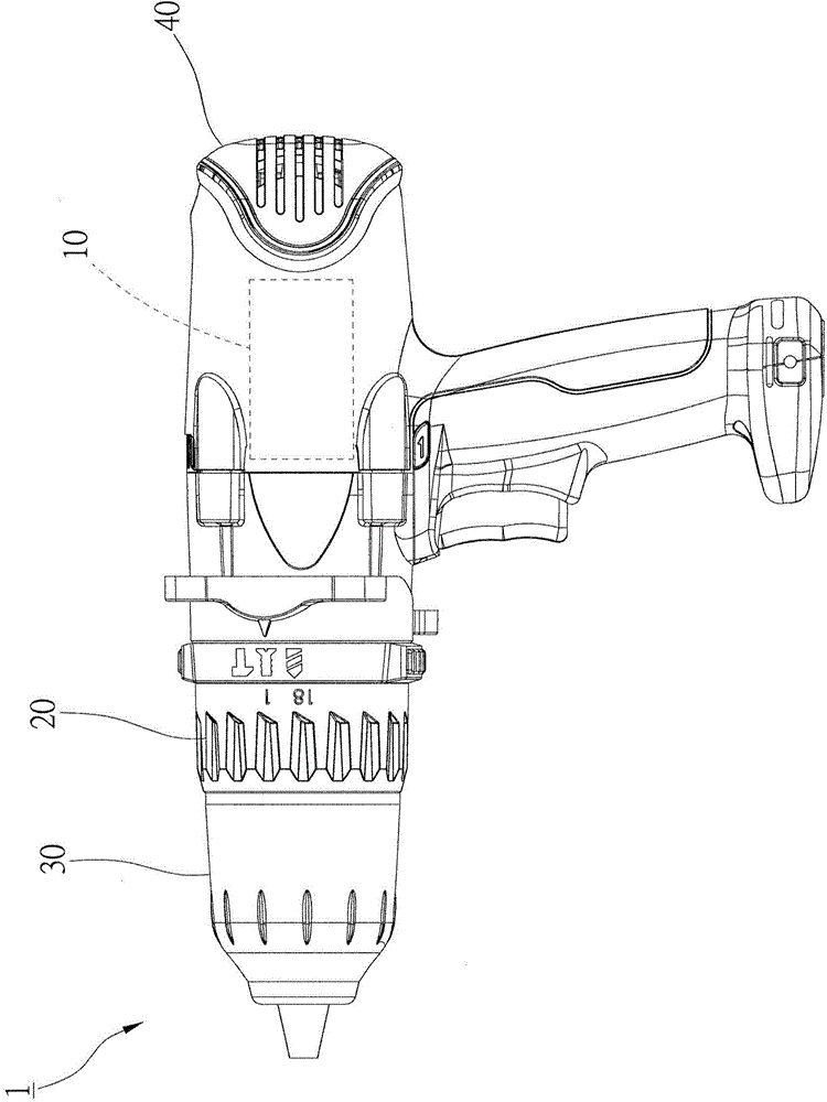
[0056] In order to illustrate the present invention more clearly, preferred embodiments are given together with diagrams in detail as follows. figure 1 It is a side view of an electric tool according to an embodiment of the present invention. The electric tool 1 includes an electric motor 10 , a torque switching device 20 , a chuck 30 and a housing 40 . Parts of the electric motor 10 and the torque switching device 20 are disposed in the casing 40 .

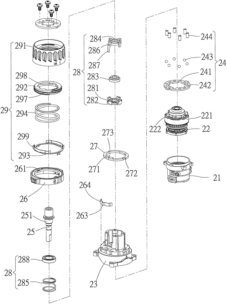
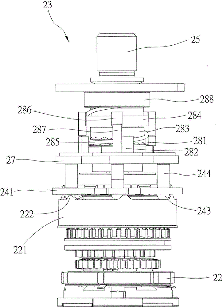
[0057] figure 2 The shown torque switching device 20 includes a gear box 21, a speed change gear set 22, a base 23, a jump gear mechanism 24, a main shaft 25, a switching button 26, a switching ring 27, an impact mechanism 28, a Torque adjustment mechanism 29.

[0058] The speed change gear set 22 is disposed in the gear box 21 , and the output shaft (not shown) of the electric motor 10 is connected to the speed change gear set 22 of the torque switching device 20 . One end of the spindle 25 is connected to the transmission ...


PUM


Abstract

The invention relates to an electric tool and a torsion switching device thereof. The electric tool comprises a shell. The torsion switching device comprises a pedestal, an inner gear ring, a switching ring and a plurality of pressing parts, wherein the pedestal is arranged inside the shell and is provided with a limiting part; the inner gear ring is arranged inside the shell, and one end face of the inner gear ring is in the face of the pedestal; the switching ring can be combined on the pedestal in the mode of rotating along a fixed axis between a first position and a second position of the pedestal, and the switching ring is provided with a positioning part; and the pressing parts are arranged between the inner gear ring and the switching ring, and one end of each pressing part abuts again the end face of the inner gear ring. When the switching ring is located at the first position, the positioning part is far away from the limiting part, and the switching ring can move in the axial direction of the pedestal. When the switching ring is located at the second position, the positioning part can be limited by the limiting part of the pedestal, and the switching ring cannot move in the axial direction of the pedestal.

Description

technical field [0001] The invention relates to a portable electric tool; in particular, it refers to an electric tool with adjustable torque function and a torque switching device thereof. Background technique [0002] Electric tools such as electric drills can be roughly divided into hand drills, impact drills, hammer drills, etc. Among them, impact drills should be the most frequently used electric tools. As the name implies, an impact drill is an electric tool that provides a hammering function while performing electric drilling operations. Impact drills are very similar to ordinary electric drills in appearance, and both have the design of changing front-end accessories. Users can attach screwdrivers, drill bits or grinding tools according to different needs. [0003] Generally speaking, impact drills generally have lock screw gears, electric drill gears and impact gears. When using the screw gear, the control gear must be adjusted to the screw gear; at this time, th...

Claims


Application Information

Patent Timeline
Patent Type & Authority Applications(China)
IPC IPC(8): B25F5/00
Inventor 郭东钦
Owner MOBILETRON ELECTRONICS
Learn More