A method for installing a ship stern shaft

An installation method and a technology of the stern shaft, which are applied in ship construction, ship design, ship parts, etc., can solve the problems of occupying resources of heavy flatbed trucks, increasing the workload of welding and removing lifting codes, and low operability accuracy of heavy flatbed trucks

Active Publication Date: 2018-07-17
GUANGZHOU SHIPYARD INTERNATIONAL LTD
View PDF5 Cites 0 Cited by
  • Summary
  • Abstract
  • Description
  • Claims
  • Application Information

AI Technical Summary

Problems solved by technology

In the case of such a weight but small precision requirements, the installation of the stern shaft is extremely difficult
[0003] The existing stern shaft installation methods generally use chain hoists for the whole process and rely on manual installation work. On the one hand, this requires a large number of workers and takes many days to complete the installation of a stern shaft, resulting in The labor cost is high and the work efficiency is low; on the other hand, in order to complete the installation of the stern shaft, multiple hand chain hoists need to be used, and the use of these hand chain hoists must weld a large number of hanging codes on the hull, which greatly increases the welding time. , The workload of removing the hanging code and subsequent paint repairs, if improper operation occurs, it may even affect the safety performance of the ship
[0004] Another installation method is to use a heavy-duty flatbed truck to assist the hand chain hoist to carry out operations. Although this can reduce the difficulty of operation to a certain extent, it takes up the resources of the heavy-duty flatbed truck and increases the cost of equipment. Furthermore, the operability of the heavy-duty flatbed truck Extremely low and not well suited for thru-shaft work with low-clearance shaft holes

Method used


Image

  • A method for installing a ship stern shaft
  • A method for installing a ship stern shaft
  • A method for installing a ship stern shaft

Examples


Embodiment Construction

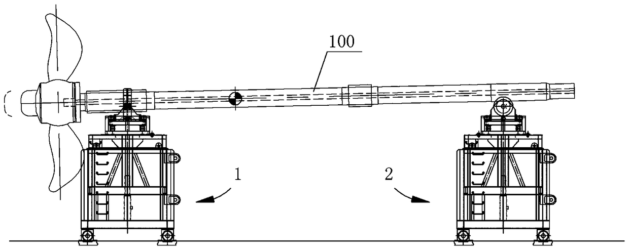
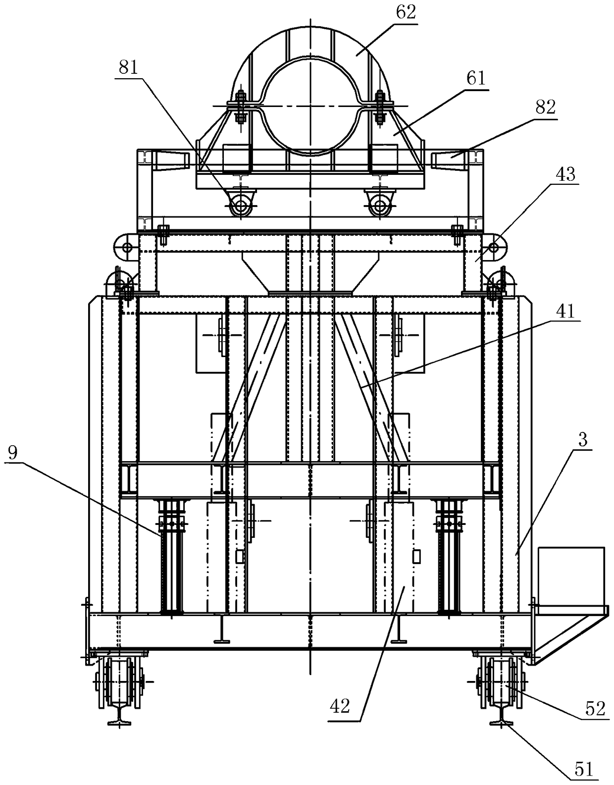
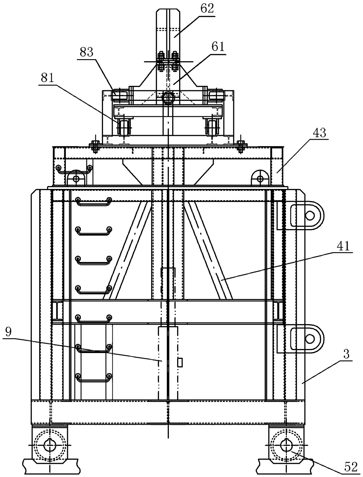
[0021] A ship stern shaft installation device, comprising a supporting trolley 1 supporting the tail end of the stern shaft 100, and a guiding trolley 2 guiding the front end of the stern shaft; The bottom of the car base is installed with a wheel assembly that drives the car base to move; the top of the jacking assembly that supports the trolley is installed with a clamp assembly that clamps and fixes the stern shaft, and the top of the jacking assembly that guides the trolley is installed. There is a roller assembly supporting the stern shaft; in addition, a lateral adjustment assembly for horizontally adjusting the clamp assembly and the roller assembly is respectively installed on the car base of the supporting trolley and the guiding trolley.

[0022] In the ship stern shaft installation device, the jacking assembly includes a jacking frame 41 that moves up and down along the vehicle base 3 and a jacking driver 42 that drives the jacking frame to move, and the top of the j...


PUM


Abstract

A method for installing a stern shaft of a ship. A supporting trolley and a guiding trolley are respectively arranged at the tail end and the front end of the stern shaft, and the two trolleys drive the stern shafts to be installed one by one on the stern shaft frame on the ship. Through the installation method of the ship stern shaft, the installation of the stern shaft can be completed conveniently and quickly, which greatly reduces the need for the use of manual hoists, and does not require heavy flatbed trucks for assistance, which can not only reduce the difficulty of installation, but also greatly improve work efficiency .

Description

technical field [0001] The invention relates to a ship manufacturing process, in particular to an installation method for installing a ship stern shaft. Background technique [0002] The stern shaft is also known as the "stern shaft", which is an important device installed at the bottom of the ship. One end is connected to the propeller, and the other end is connected to the gearbox or coupling and then connected to the engine. The engine drives the propeller to rotate through the stern shaft to drive the ship to sail. . In large ships, the stern shaft generally reaches more than 50 tons, even more than 80 tons, and the length is more than 18 meters. The gap between the stern shaft and the shaft hole is generally about 0.05~0.07mm. With such a weight but small precision requirements, the installation of the stern shaft is extremely difficult. [0003] The existing stern shaft installation methods generally use chain hoists for the whole process and rely on manual installat...

Claims


Application Information

Patent Timeline
Patent Type & Authority Patents(China)
IPC IPC(8): B63B9/00
CPCB63B71/00
Inventor 韦青嵩李金兰何志年卜佑天陈雄剑姚杰
Owner GUANGZHOU SHIPYARD INTERNATIONAL LTD
Why Eureka
Try Eureka