
Broken strap seizing device for belt

A belt and conveying roller technology, applied in the field of belt-broken belt catching devices, can solve the problems of complex operating environment, small braking area, and malfunction, and achieve the effect of simple triggering principle, accurate signal, and rapid action.

Active Publication Date: 2016-11-23
江苏中航重工机床有限公司
View PDF7 Cites 0 Cited by
  • Summary
  • Abstract
  • Description
  • Claims
  • Application Information

AI Technical Summary

Problems solved by technology

In recent years, mechanical, hydraulic and other broken belt protection devices have appeared at home and abroad, but from the actual use situation, they are far from meeting the requirements of on-site use. The main shortcomings are as follows: relying on the reverse movement generated by the broken belt to trigger the catcher action, due to the complexity of the operating environment
[0003] Sexuality leads to malfunction and affects production
The actuator of the catcher adopts a brake block or an eccentric wheel mechanism, the braking area is small, the braking force is concentrated, and it is easy to cause the tape to tear

Method used


Image

  • Broken strap seizing device for belt

Examples


Embodiment Construction

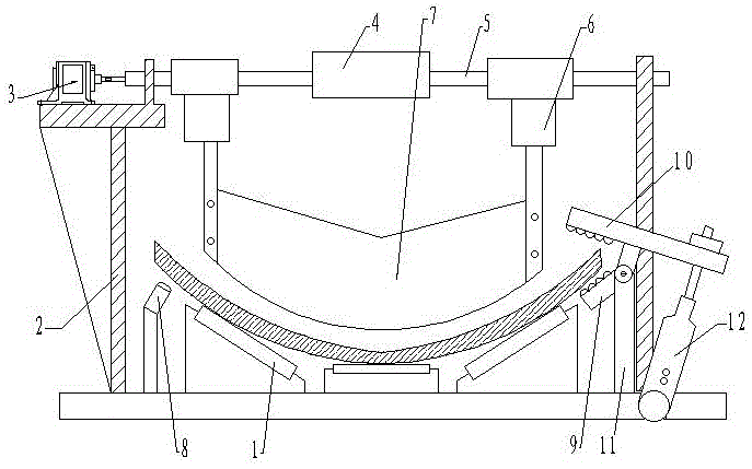
[0008] Such as figure 1 As shown, a broken belt arresting device, which includes a belt transmission drum frame 1, a frame-shaped support frame 2, a frequency conversion motor 3, a backstop 4, a transmission shaft 5, a telescopic cylinder 6, a coal shovel plate 7, a speed measuring Sensor 8, belt catching device, a speed measuring sensor 8 for measuring belt transmission speed change is fixed on one side of the belt transmission drum frame 1, and at least one belt catching device is fixed on the other end of the belt transmission drum frame 1, so Described belt capture device is made up of lower splint 9, upper splint 10, support 11 and oil cylinder 12, and support 11 is fixed on the belt conveying roller frame 1, and lower splint 9 is fixed on the upper end of support 11, and upper splint 10 is relative to lower splint 9. It is rotatably fixed on the bracket 11 through the rotating shaft, and the upper splint 10 is driven and rotated by the oil cylinder 12, wherein the clampi...


PUM


Abstract

The invention relates to a broken strap seizing device for a belt. One side of a belt conveying rolling barrel frame is fixedly provided with a speed measuring sensor used for measuring the change of the transmission speed of the belt, while the other end of the belt conveying rolling barrel frame is fixedly provided with a belt seizing device; the belt seizing device consists of a lower clamping plate, an upper clamping plate, a bracket and an oil cylinder; the bracket is fixedly arranged on the belt conveying rolling barrel frame; the lower clamping plate is fixedly arranged at the upper end of the bracket; the upper clamping plate is rotatably fixedly arranged, relative to the lower clamping plate, on the bracket through a rotating shaft; the upper clamping plate is pushed to rotate by the oil cylinder; two sides of the belt conveying rolling barrel frame are provided with a framework-shaped supporting frame; a transmission shaft is transversely erected on the framework-shaped supporting frame; the middle part of the transmission shaft is fixedly provided with a back stopper; two ends, which are located on the back stopper, of the transmission shaft are provided with a telescopic cylinder respectively; telescopic ends of the telescopic cylinders are fixed with a coal shoveling plate; and the transmission shaft is driven by a variable-frequency motor fixedly arranged on one side of the framework-shaped supporting frame. The quick and reliable seizing is utilized for the broken strap seizing device for the belt; a seizing shoe is reasonably designed; and the seizing damage cannot be generated to a transporting strap.

Description

technical field [0001] The invention belongs to the field of mine conveying equipment, and in particular relates to a broken belt arresting device. Background technique [0002] As the main conveying equipment for bulk and bulk materials, belt conveyors have been widely used in industries such as coal, cement, electric power, chemical industry, ports and building materials. However, for a belt conveyor with a large inclination angle, once a broken belt accident occurs, the conveyor frame will be destroyed, the auxiliary equipment will be damaged, and the transportation roadway will be blocked, resulting in long-term production stoppage and major economic losses, and even casualties, which are extremely destructive. serious. There are many relevant casualty data reports in this area both at home and abroad. At present, the most important protection measure for conveyor belt fracture accidents is to install a broken belt protection device on the conveyor, also known as a cat...

Claims


Application Information

Patent Timeline
Patent Type & Authority Applications(China)
IPC IPC(8): B65G43/06
CPCB65G43/06B65G2207/40Y02P70/10
Inventor 李文杰
Owner 江苏中航重工机床有限公司
Learn More