Fully-assembled plate column structure and fully-assembly floor system composed of same

A technology for assembling slab and column structures, applied in the direction of floor slabs, building components, building structures, etc., can solve problems such as stress concentration of beam-column joints, and achieve the effects of stress dispersion, cost reduction, and construction period shortening

Inactive Publication Date: 2016-11-23
SICHUAN INSITITUTE OF BUILDING RES
View PDF11 Cites 10 Cited by
  • Summary
  • Abstract
  • Description
  • Claims
  • Application Information

AI Technical Summary

Problems solved by technology

[0003] The invention provides a fully assembled slab-column structure, which solves the problem of stress concentration at beam-column joints, can be quickly assembled and formed, and saves construction time

Method used


Image

  • Fully-assembled plate column structure and fully-assembly floor system composed of same
  • Fully-assembled plate column structure and fully-assembly floor system composed of same
  • Fully-assembled plate column structure and fully-assembly floor system composed of same

Examples


Embodiment 1

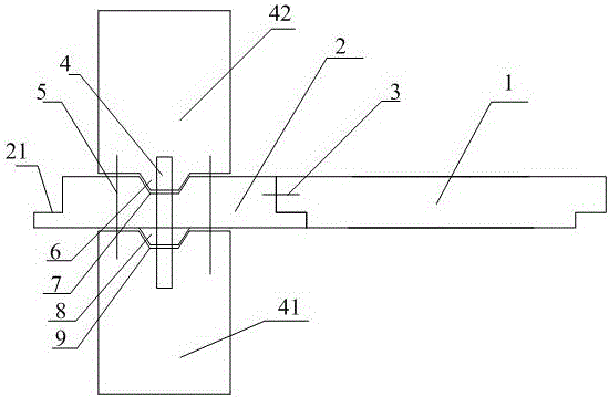
[0025] Such as Figure 1-Figure 2 as shown,

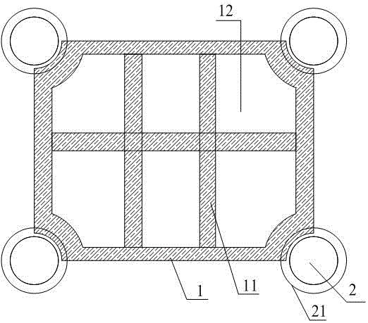
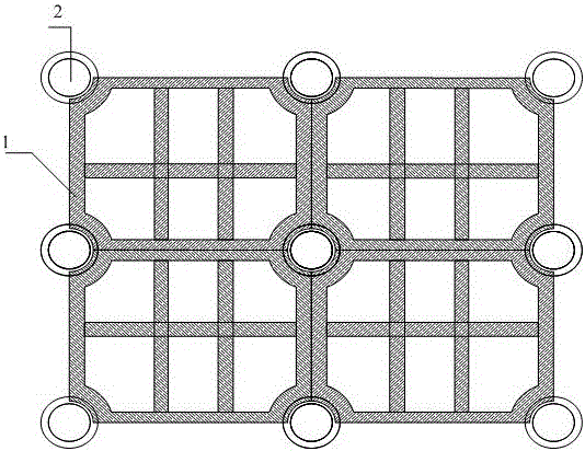
[0026] Fully assembled slab-column structure, including a support column structure, the support column structure includes a column cap 2 located between the upper column 41 and the lower column 42, the column cap 2 is a fan-shaped structure, and the arc-shaped outer wall of the column cap extends outward to form a brim 21, also includes the floor, any corner of the floor is concaved into an arc-shaped corner, and one corner of the floor is lapped on the brim 21 so that the arc-shaped corner of the floor matches the arc-shaped outer wall of the column cap 2. This technical solution adopts the design principle of direct lapping between the column cap structure and the floor slab, uses the column cap structure and uses the brim set by the column cap structure as a supporting structure, the floor is directly erected on the eaves, and uses the column cap 2 as a fan-shaped structure or a circular structure The particularity of the hat b...

Embodiment 2

[0029] The difference between this embodiment and embodiment 1 is:

[0030] The column cap 2 is a quarter-circle fan-shaped structure, and the brim 21 is also a quarter-circle fan-shaped structure.

Embodiment 3

[0032] The difference between this embodiment and embodiment 1 is:

[0033] The column cap 2 is a fan-shaped structure of a half circle, and the brim 21 is also a fan-shaped structure of a half circle.

[0034] Example 3

[0035] The difference between this embodiment and embodiment 1 is:

[0036] The column cap 2 has a semicircular fan-shaped structure, and the brim 21 also has a semicircular fan-shaped structure.

[0037] Example 3

[0038] The difference between this embodiment and embodiment 1 is:

[0039] The column cap 2 has a circular structure, and the brim 21 also has a circular structure.


PUM


Abstract

The invention discloses a fully-assembled plate column structure which comprises a supporting column structure. The supporting column structure comprises a column cap located between an upper column and a lower column. The column cap is of a fan-shaped structure or circular structure. The arc-shaped outer side wall of the column cap extends outwards to form a cap eave. The supporting column structure further comprises a floor. Any corner of the floor is indented to form an arc-shaped corner. One corner of the floor is in lap joint with the cap eave so that the arc-shaped corner of the floor can be matched with the arc-shaped outer side wall of the column cap. The fully-assembled plate column structure has the advantages that a prefabricated structure floor is adopted as the floor, the column cap is of a prefabricated structure, prefabricated columns or cast-in-place columns can be adopted as the upper column and the lower column, and the whole structure is combined and formed in an assembly mode; through the arc-shaped structure characteristic of the column cap and the cap eave and the lap joint matching of the arc-shaped corner of the floor, stress is dispersed, beam structures are omitted, cost is reduced, the plate column structure can be rapidly assembled, and the construction cycle can be greatly shortened.

Description

technical field [0001] The invention relates to the field of building technology, in particular to a fully assembled slab-column structure and the fully assembled floor system technology formed therefrom. Background technique [0002] In building construction, the structure of the building is composed of columns, beams, and floors. The beams and columns are connected, and the connection points are beam-column joints. Column joints, while the floor slab is formed directly on the adjacent beams. This method has a long construction period, a large waste of materials, and the stress of the beam-column joints is easy to concentrate and easy to break. Contents of the invention [0003] The invention provides a fully assembled slab-column structure, which solves the problem of stress concentration at beam-column joints, can be quickly assembled and formed, and saves construction time. [0004] Fully assembled slab-column structure, including the support column structure, the sup...

Claims


Application Information

Patent Timeline
Patent Type & Authority Applications(China)
IPC IPC(8): E04B1/21E04B5/02
CPCE04B1/21E04B5/02
Inventor 张瀑鲁兆红黄爱萍
Owner SICHUAN INSITITUTE OF BUILDING RES
Why Eureka
Try Eureka