Fixing structure for lifting rope of beam-pumping unit

A technology of beam pumping unit and fixed structure, which is applied in the fields of mining fluid, wellbore/well parts, earthwork drilling and production, etc., which can solve the problem of not easy to find small cracks in the donkey head, easy cracks in the donkey head, and potential safety hazards, etc. Problems, to achieve the effect of reducing maintenance costs in the later period, not easy to wear, and not easy to abnormal noise

Active Publication Date: 2016-11-23
CHINA PETROLEUM & CHEM CORP +1
View PDF5 Cites 0 Cited by
  • Summary
  • Abstract
  • Description
  • Claims
  • Application Information

AI Technical Summary

Problems solved by technology

[0003] 1. Since the sling is directly placed on the top of the donkey's head, the pulling force on the sling is all borne by the donkey's head, and the middle part of the donkey's head is provided with a notch for connecting the beam. In this way, after a period of use, the donkey's head will It is very easy to produce cracks, which poses a safety hazard; at the same time, due to the high position of the donkey's head, it is difficult for the staff to find small cracks on the donkey's head during daily inspections. Generally, when they are found, the cracks have expanded to a very serious level. There may even be serious accidents in which the donkey head falls from a height to the ground;
[0004] 2. Since the pulling force on the sling is all borne by the donkey head, the donkey head tends to move relative to the beam. In this way, after a period of use, the donkey head pin is easy to wear and loose in the pin hole, and then abnormal ring

Method used


Image

  • Fixing structure for lifting rope of beam-pumping unit
  • Fixing structure for lifting rope of beam-pumping unit
  • Fixing structure for lifting rope of beam-pumping unit

Examples


Embodiment Construction

[0034] In order to make the object, technical solution and advantages of the present invention clearer, the implementation manner of the present invention will be further described in detail below in conjunction with the accompanying drawings.

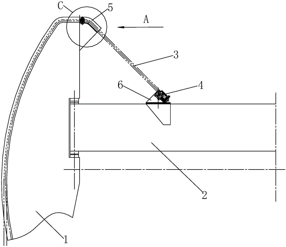
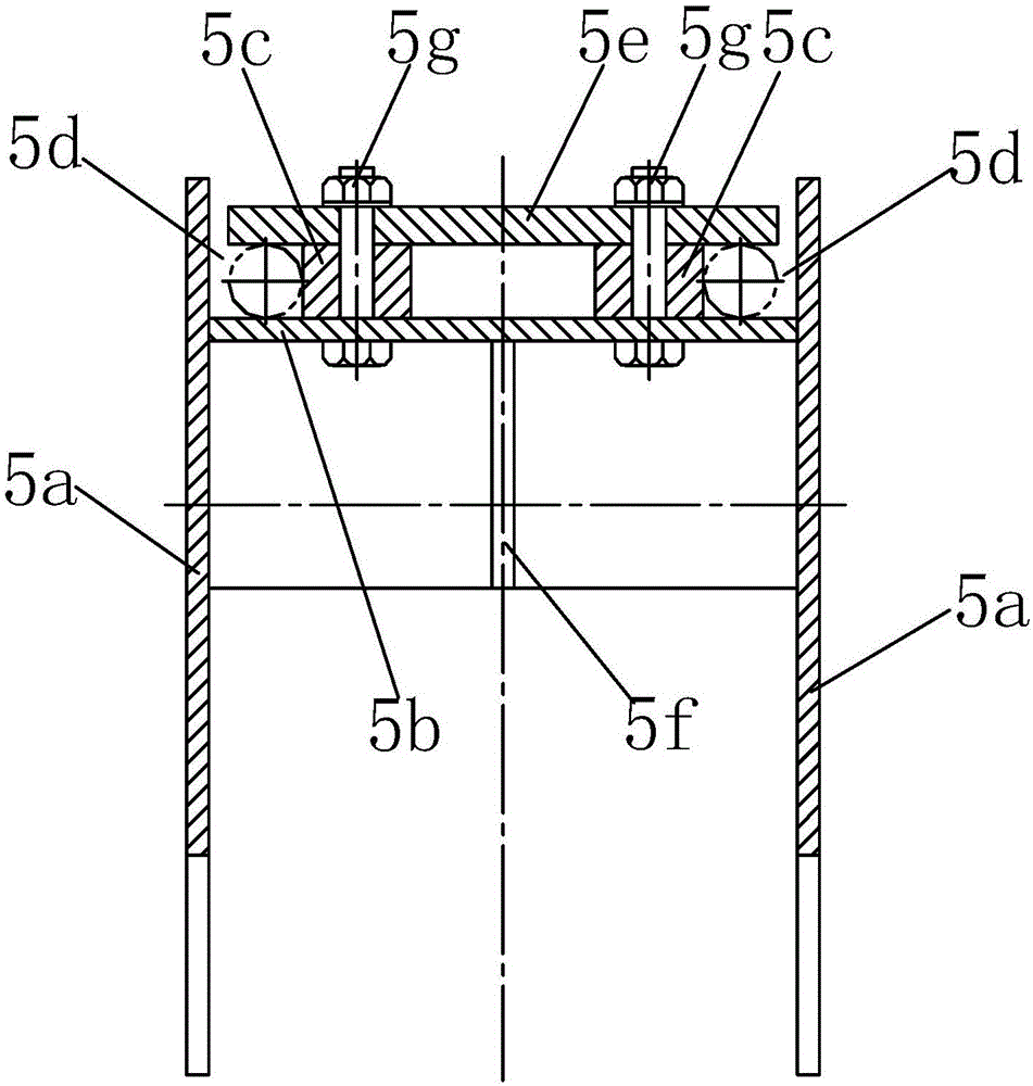
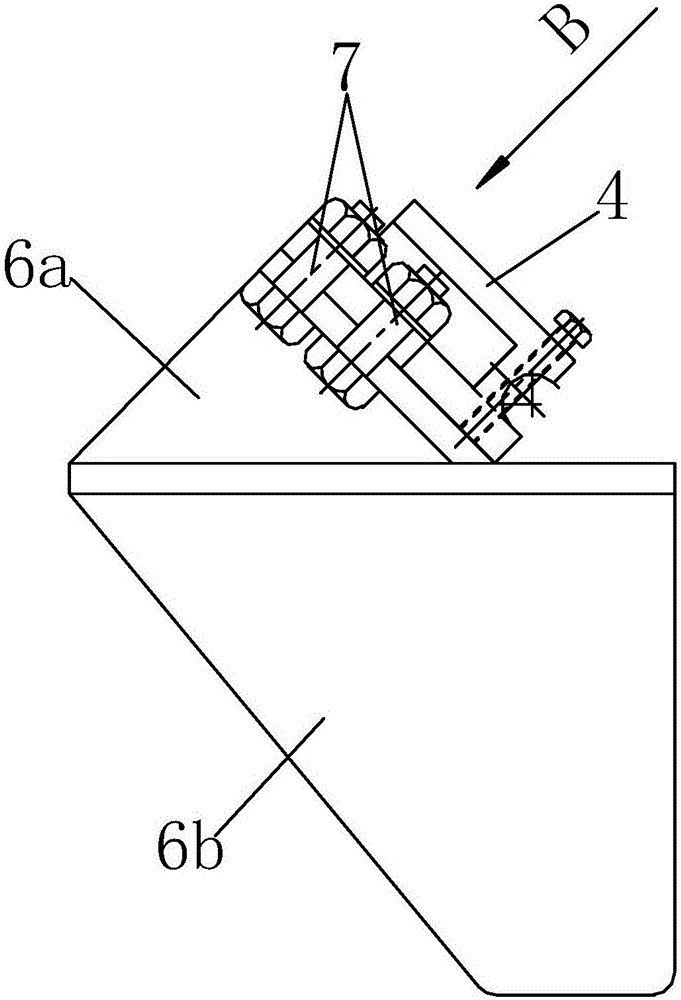
[0035] Such as figure 1 As shown, a suspension rope fixing structure of a beam pumping unit provided by the present invention includes: a donkey head 1, a beam 2, a suspension rope 3 and a rope hanger 4, and the beam 2 and the donkey head 1 Connected, the top of the donkey head 1 is provided with a transition guide bracket 5 for guiding and limiting the suspension rope 3, and the rope hanger 4 is obliquely installed on the beam 2 through the auxiliary support 6. The entrance and exit rope opening of the rope hanger 4 is arranged towards the transition guide bracket 5; the transition guide bracket 5 includes side plates 5a installed on both sides of the top of the donkey head 1 respectively, between two side plates 5a An arc-shaped gui...


PUM


Abstract

A fixing structure for a lifting rope of a beam-pumping unit comprises a horse head and a beam, wherein the beam is connected with the horse head, a transition guide support is arranged at the top of the horse head, a rope hanging device is mounted on the beam through an auxiliary supporting seat, and a rope inlet and a rope outlet of the rope hanging device face the transition guide support; the transition guide support comprises side plates mounted on two sides of the top of the horse head respectively, a cambered guide bottom plate is mounted between the two side plates, limit blocks are mounted on the cambered guide bottom plate, limit grooves are defined by the limit blocks, the cambered guide bottom plate and the corresponding side plates, a limit pressure plate is arranged on the limit blocks, and a reinforcing supporting plate is arranged between the bottom surface of the cambered guide bottom plate and a corresponding position on the horse head; the auxiliary supporting seat comprises a supporting seat body and a reinforcing plate, the lower part of the supporting seat body is mounted on the beam through the reinforcing plate, an inclined mounting plane is arranged at the upper part of the supporting seat body, and the rope hanging device is mounted on the inclined mounting plane; one end of the lifting rope penetrates one limit groove, then goes into the rope inlet of the rope hanging device and goes out of the rope outlet of the rope hanging device and finally back penetrates the other limit groove. The fixing structure is applicable to the beam-pumping unit.

Description

technical field [0001] The invention relates to a suspension rope fixing structure of an oil pumping unit, in particular to a suspension rope fixing structure of a beam pumping unit. Background technique [0002] At present, the beam pumping unit is the type of pumping unit with the largest number of applications and the widest distribution. This kind of beam pumping unit generally includes a bracket, a beam, a driving mechanism, a donkey head and a suspension rope. The middle part of the beam is hinged on the bracket, one end of the beam is connected to the driving mechanism, and the other end of the beam is connected to the vertical The middle part of the donkey's head is connected, the donkey's head and the beam are connected and fixed by the donkey's head pin, and the sling is arranged on the top of the donkey's head through a rope hanger. The beam pumping unit with this structure has the following problems in actual use: [0003] 1. Since the sling is directly placed ...

Claims


Application Information

Patent Timeline
Patent Type & Authority Applications(China)
IPC IPC(8): E21B43/00
CPCE21B43/12E21B43/127
Inventor 何家钧潘军李彪毛家友杨涛
Owner CHINA PETROLEUM & CHEM CORP
Why Eureka
Try Eureka