Automatic cleaning device for evaporating pot heat exchange tube

A technology for automatic cleaning and heat exchange tubes, which is applied in the direction of cleaning heat transfer devices, flushing, lighting and heating equipment, etc. It can solve the problems of complex structure and limited cleaning range, and achieve the effect of expanding the use range and improving the stress situation

Active Publication Date: 2014-03-26
GUANGXI UNIV
View PDF10 Cites 25 Cited by
  • Summary
  • Abstract
  • Description
  • Claims
  • Application Information

AI Technical Summary

Problems solved by technology

[0004] In the prior art, the evaporating tank cleaning equipment has problems such as limited cleaning range and complicated structure. In order to solve the above technical problems, the present invention adopts the following technical solutions: an automatic cleaning device for the heat exchange tube of the evaporating tank, which includes a central column, a sliding Frame driving mechanism, frame part, frame wheel part, frame driving mechanism, water pipe clamping wheel mechanism, water pipe conveying mechanism; The front frame rotating table 2.8, the rear frame 2 and the connecting frame plate 2.2; frame wheel 5.5; the frame drive mechanism at least includes f

Method used


Image

  • Automatic cleaning device for evaporating pot heat exchange tube
  • Automatic cleaning device for evaporating pot heat exchange tube
  • Automatic cleaning device for evaporating pot heat exchange tube

Examples


Embodiment Construction

[0026] The present invention will be described in further detail below in conjunction with the accompanying drawings and specific embodiments.

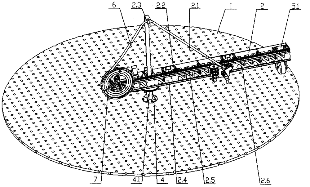
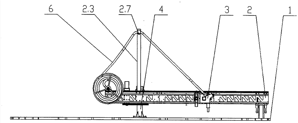
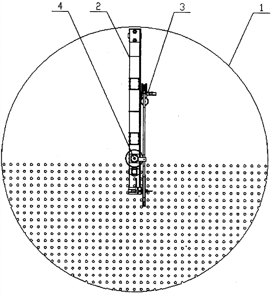
[0027] The automatic cleaning device for the heat exchange tube of the evaporation tank of the present invention, such as figure 1 , figure 2 and image 3 shown, where figure 1 The top surface of the medium evaporator 1 is all nozzles with heat exchange tubes distributed therein. For clarity, image 3 Only half of it is represented by ellipsis. The front frame rotating table 2.8 of the frame part is installed on the front frame 2.4 and is hinged with the center column 4, and the center column 4 is installed in the center of the evaporation tank 1 under the working state; the end of the rear frame 2 is connected with the frame wheel part Positioning connection, frame wheel 5.5 walks on evaporation tank 1, this part is as follows Figure 4 Shown; Cleaning machine head 3 is housed on the frame part; Guide wheel frame 2.3 is equippe...


PUM


Abstract

The invention discloses an automatic cleaning device for an evaporating pot heat exchange tube. The automatic cleaning device comprises a center column, a sliding fame driving mechanism, a machine frame portion, a machine frame wheel portion, a machine frame driving portion, a water pipe clamping wheel mechanism and a water pipe conveying mechanism; one end of the machine frame portion is hinged to the center column, the other end of the machine frame portion is connected with the machine frame wheel portion in a positioned mode, and the length of the machine frame portion can be changed by adding a connection machine frame portion; the machine frame driving mechanism is arranged a front machine frame of the machine frame portion and drives the machine frame portion to rotate around the center column, the sliding frame driving mechanism drives the water pipe clamping mechanism to slide on the side face of the machine frame portion, and the heat exchange tube is positioned in a polar coordinate mode; the water pipe conveying mechanism and the water pipe clamping mechanism are combined to achieving conveying and retracting of a water pipe. The automatic cleaning device for the evaporating pot heat exchange tube can achieve automatic cleaning, the length of the machine frame portion can be enlarged according to the size of an evaporating pot, no cleaning dead space exist in a cleaning range, and the phenomenon that machine frame wheels are blocked because of walking on the surface of an irregular evaporating pot can be avoided.

Description

technical field [0001] The invention relates to the field of cleaning evaporation tanks, and is particularly suitable for cleaning tube-and-tube heaters by high-pressure water jets. technical background [0002] In actual production, due to the influence of the sugar refining process in the sugar factory, after a period of use, the tube heater will deposit calcium sulfite scale with uneven thickness on the inner wall of the tube. Fouling greatly reduces the heat transfer efficiency of the heater, which directly affects the normal progress of the sugar making process. Therefore, it is necessary to descale the heat exchange tubes of the evaporating tank. In the past, chemical descaling methods, manual machinery and high-pressure water cleaning were generally used. The chemical descaling method is time-consuming, high in cost, and corrodes the heat exchange tubes. Manual machinery and high-pressure water cleaning are labor-intensive, inefficient, and unsafe. The tube heaters...

Claims


Application Information

Patent Timeline
IPC IPC(8): F28G9/00F28G15/02F28G15/04
Inventor 潘海鸿叶文海陈琳韦国琪黄炳琼
Owner GUANGXI UNIV
Why Eureka
Try Eureka