
Two-way work doing driving mechanism and portable self-aid generating and lighting device

A transmission mechanism, one-way transmission technology, applied in portable lighting devices, lighting devices, lighting devices, etc., can solve problems such as damage to emergency lighting equipment, unstable current output, limited service life, etc., to expand the audience and use range. , the power output is uniform, the effect of good water tightness

Inactive Publication Date: 2005-10-19
石为民 +2
View PDF0 Cites 25 Cited by
  • Summary
  • Abstract
  • Description
  • Claims
  • Application Information

AI Technical Summary

Problems solved by technology

Due to the intolerance of storage, dry batteries will even damage emergency lighting equipment if they are not used for a long time, and the used dry batteries will bring huge environmental pollution. This problem has not yet been found a proper solution; and the battery is due to its large size and weight. , so that it is not very convenient to use and carry, and its service life of repeated charging is also quite limited; more importantly, these energy storage emergency devices lose their function after the stored electric energy is exhausted, and cannot really work. to the role of "emergency"
An emergency lighting device that uses manpower to do reciprocating motions (such as opening and closing handles, etc.) to generate electricity has also been proposed, but due to the unreasonable structure, the energy generated by manpower cannot meet the needs of normal lighting at all.
[0003] The existing reciprocating transmission mechanism generally only works effectively when moving in the set direction, and idles during the reset process. This method not only wastes half of the energy, but also uses the output energy for When generating electricity, the current output will be very unstable, which is not conducive to the further utilization of the current

Method used


Image

  • Two-way work doing driving mechanism and portable self-aid generating and lighting device
  • Two-way work doing driving mechanism and portable self-aid generating and lighting device
  • Two-way work doing driving mechanism and portable self-aid generating and lighting device

Examples


Embodiment 1

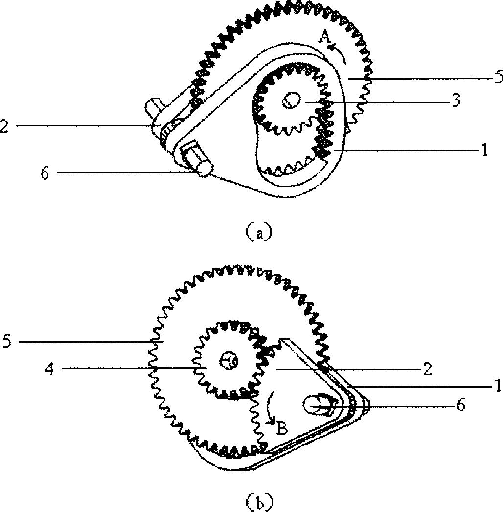
[0030] Embodiment 1. A two-way power transmission mechanism, combined with figure 1 (a), (b), including the arc-shaped tooth groove 1 and the arc-shaped gear piece 2 used as a power input device, the first ratchet device 3 and the second ratchet device 4 used as a one-way transmission member, and used as a power output The primary gear 5 of the device. The arc-shaped tooth groove 1 and the arc-shaped gear piece 2 are arranged coaxially, and can swing synchronously around the axis; the first ratchet device 3 and the second ratchet device 4 are arranged coaxially with the primary gear 5, and the two ratchet devices are single To drive the first-stage gear 5, the one-way drive means that when the two ratchet devices rotate along the set direction (clockwise in this example), it engages with the first-stage gear 5 for transmission, when the two ratchets When the device moves in the reverse direction, the engagement is disengaged; the arc-shaped tooth groove 1 inwardly engages the...

Embodiment 2

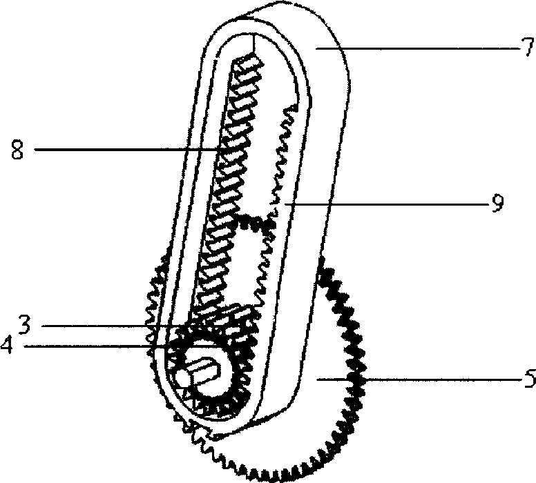
[0032] Embodiment two, another kind of two-way power transmission mechanism, combined figure 2 with image 3 , including a double-sided rack 7 used as a power input device, a first ratchet device 3 used as a one-way transmission member, a second ratchet device 4, and a primary gear 5 used as a power output device. The first ratchet device 3 and the second ratchet device 4 are coaxially arranged with the primary gear 5, and the two ratchet devices drive the primary gear 5 in one direction. (Clockwise direction in this example) when it rotates, it engages with the first-stage gear 5 for transmission, and when the two ratchet devices move in the opposite direction, the engagement disengages; the first ratchet device 3 and the second ratchet device 4 are arranged on both sides Between the two sides of the rack 7, the rack parts on both sides of the bilateral rack 7 are staggered along the axial direction of the ratchet device, and the first ratchet device 3 and the second ratche...

Embodiment 3

[0034] Embodiment three, yet another two-way power transmission mechanism, combined with Figure 4 , including an arc-shaped bilateral tooth groove 10 used as a power input device, a first ratchet device 3 used as a one-way transmission member, a second ratchet device 4, and a primary gear 5 used as a power output device. The arc-shaped bilateral tooth groove 10 can reciprocate around the fixed shaft 11; the first ratchet device 3 and the second ratchet device 4 are coaxially arranged with the first-stage gear 5, and the two ratchet devices drive the first-stage gear 5 in one direction. Direct drive means that when the two ratchet devices rotate in the set direction (clockwise in this example), they are engaged with the primary gear 5 for transmission, and when the two ratchet devices move in the opposite direction, the engagement is disengaged; The first ratchet device 3 and the second ratchet device 4 are arranged between the two sides of the arc-shaped bilateral cog 10, and...


PUM


Abstract

The bi-directional work doing transmission mechanism includes power input unit, two single-way transmission parts, and power output unit to drive simultaneously these two single-way transmission parts to move oppositely. The present invention also discloses portable self-aid generating and lighting device with the bi-directional work doing transmission mechanism. The present invention is superior in that two single-way transmission parts are driven in opposite directions so that there is always one single-way transmission part to drive the power output unit during the reciprocating motion, resulting in best utilization of energy and raised transmission efficiency.

Description

【Technical field】 [0001] The invention relates to a transmission mechanism and electromechanical equipment including the mechanism, in particular to a bidirectional power transmission mechanism and a portable self-service power generation and lighting device including the mechanism. 【Background technique】 [0002] Today, with the rapid development of science and economy, emergency lighting devices still have a wide range of applications. In modern cities, due to the massive consumption of resources, power supply is often in a tense situation; while in remote and poor rural areas, imperfect power grid construction and lack of public supporting facilities make emergency lighting devices even more necessary for daily necessities. Common emergency lighting devices include flashlights, emergency lights, etc., which either use dry batteries or rechargeable batteries and other electric energy storage devices to supply electric energy when there is no external power supply. Due to ...

Claims


Application Information

Patent Timeline
Patent Type & Authority Applications(China)
IPC IPC(8): F03G5/00F21L13/00F21V33/00
Inventor 石为民连伟吕大明
Owner 石为民
Learn More