Heater device for desiccant rotor dehumidifier

a desiccant rotor dehumidifier and heating element technology, which is applied in the direction of air heaters, lighting and heating apparatus, heating types, etc., can solve the problems of uncontrollable airflow through the heating element, complex assembly, and high cost, so as to prevent thermal loss, simple construction, and uniform airflow output

Inactive Publication Date: 2006-05-23
NORM PACIFIC AUTOMATION
View PDF7 Cites 17 Cited by
  • Summary
  • Abstract
  • Description
  • Claims
  • Application Information

AI Technical Summary

Benefits of technology

[0005]The major object of the invention is to provide a heating device applicable to desiccant rotor dehumidifier that can prevent thermal loss.
[0006]Another object of the invention is to provide a heating device applicable to desiccant rotor dehumidifier that can provide uniform airflow output.
[0007]A further object of the invention is to provide a heating device applicable to desiccant rotor dehumidifier that has simple construction.
[0008]To achieve the aforesaid objects, a heater device applied in a desiccant rotor dehumidifier for supplying regeneration hot air to the desiccant rotor comprises a metal case having an air inlet and an air outlet; heating elements supported by insulative material and mounted adjacent to the desiccant rotor; and an insulative plate installed in parallel to the heating elements and parting the heating elements with the air inlet. The insulative plate is formed with a plurality of via holes suitably distributed for the intake air coming from the air inlet passing through, being heated by the heating elements and evenly passing the desiccant rotor through the air outlet. Since the insulative plate shields the thermal radiation of the heating elements to the heater case, and the air intake passing through the via holes of the insulative plate removes the heat received from the heating elements, therefore, the thermal loss is less. The via holes on the insulative plate also makes the airflow output uniform. The insulative plate and the insulative material for supporting the heating elements are made of mica or the like, which are non-metal and make the electrical insulation easy and simple. The insulative plate also splits and bypasses a part of the intake air to cool down the desiccant rotor that has been heated and regenerated.

Problems solved by technology

Though the construction can save thermal loss, the airflow passing through the heating element 9a is not controlled of its uniformity.
As a result, the supporting means for the heating element 9a (usually bare heating wire) have to be well electrically insulated that cause the assembly more complicated and costly.

Method used


Image

  • Heater device for desiccant rotor dehumidifier
  • Heater device for desiccant rotor dehumidifier
  • Heater device for desiccant rotor dehumidifier

Examples


Embodiment Construction

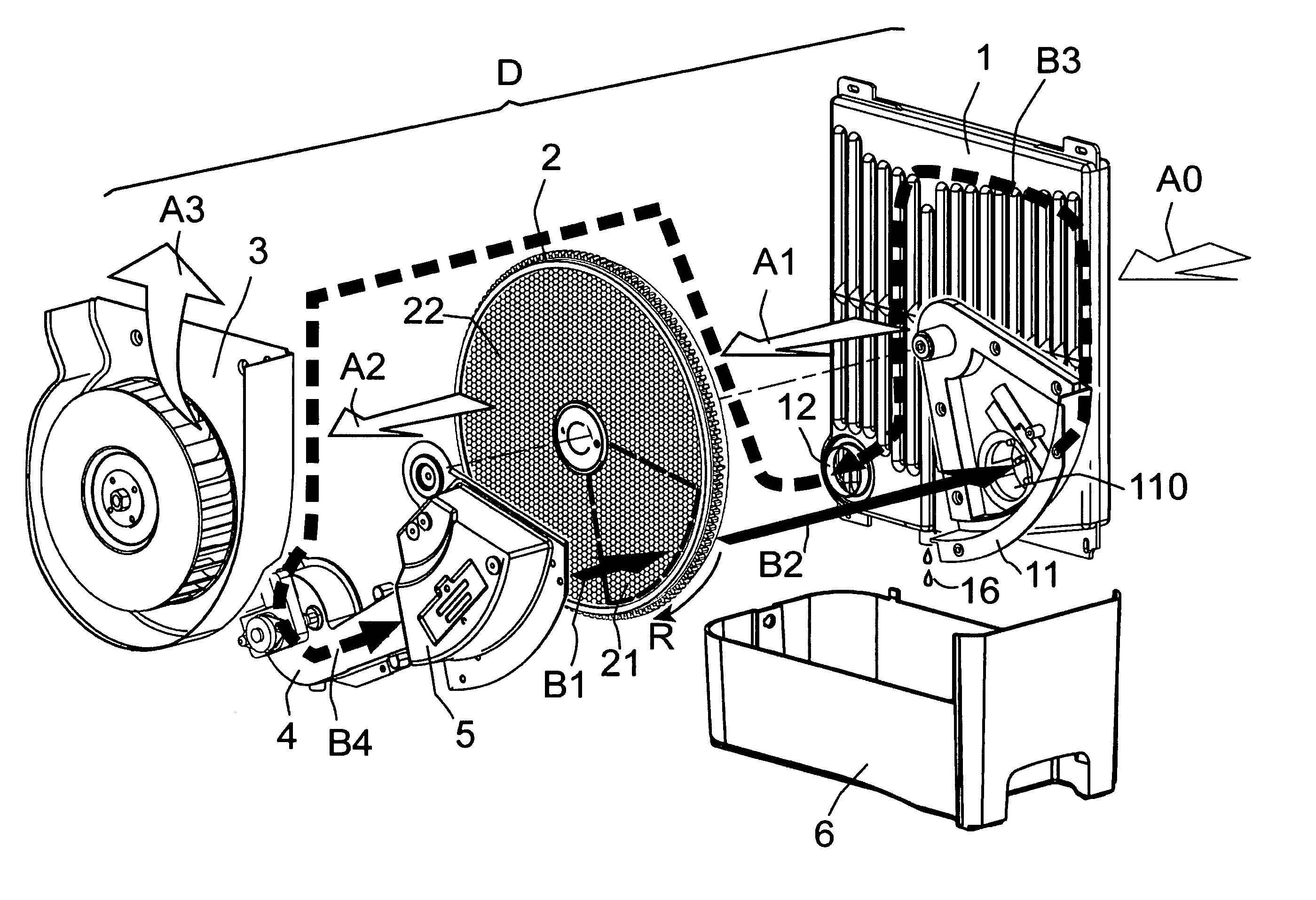
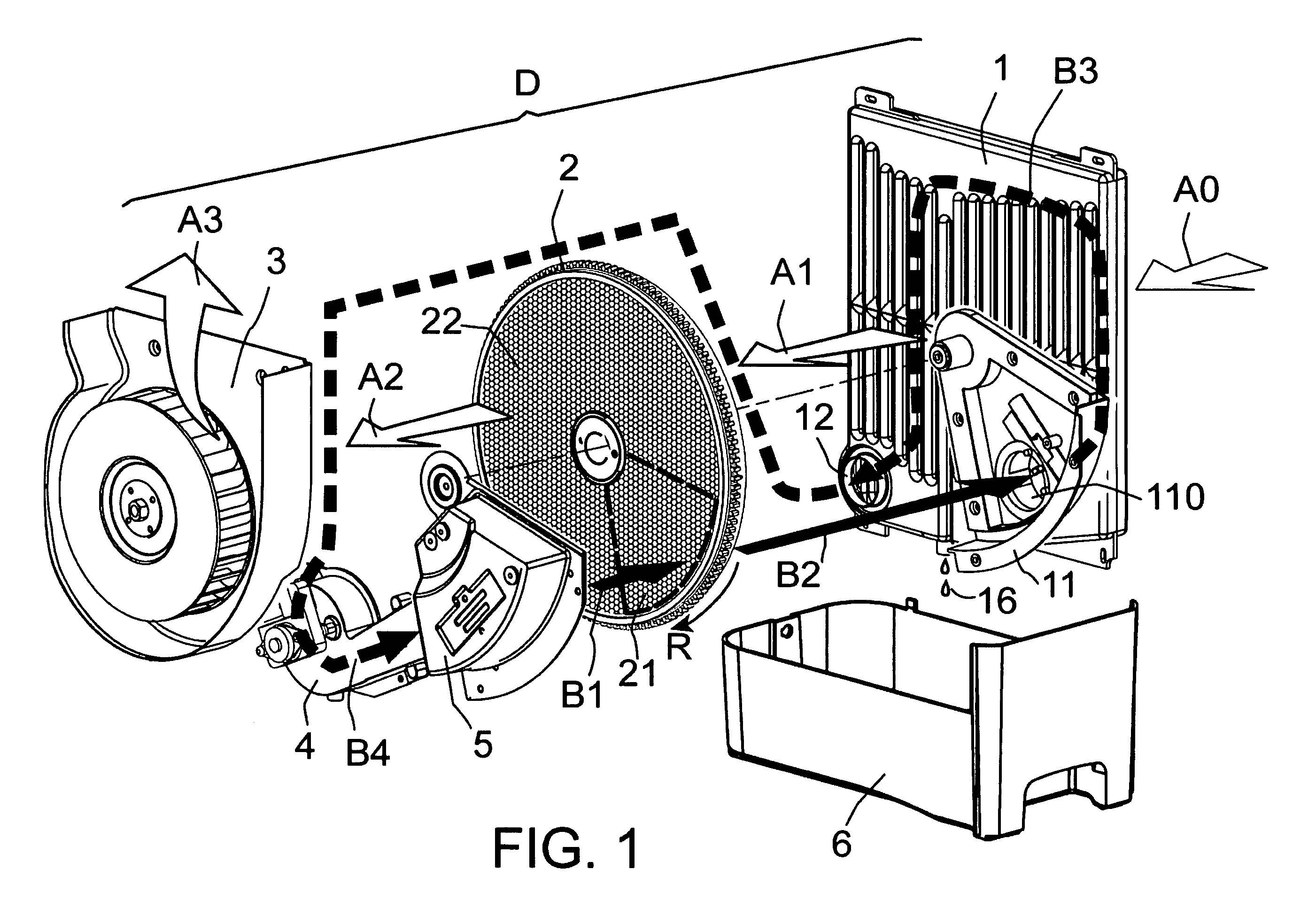
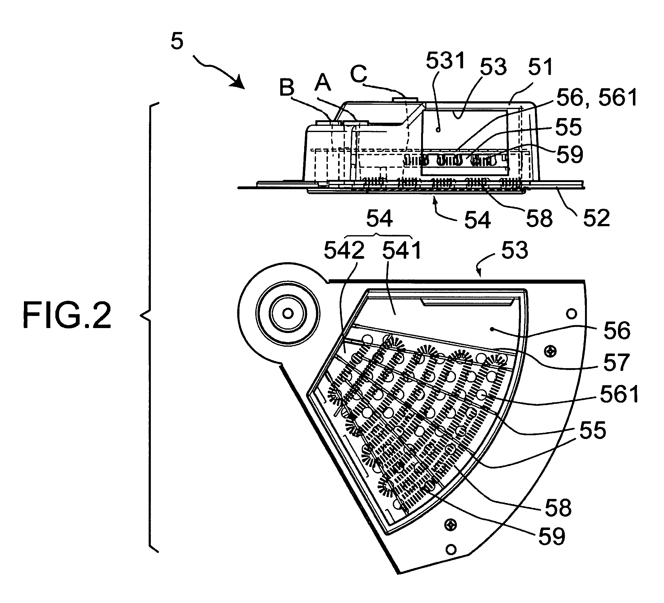
[0014]FIG. 2 is an orthographical view of a heater device of an embodiment of the invention taken from air inlet and air outlet directions. The heater device 5 is composed of a box 51 and a cover 52, which are preferably made of metal for fire retardancy. The box 51 is formed with an air inlet 53 connecting to the airflow provided by the second fan 4 (FIG. 1). The cover 52 is formed with an air outlet 54 connecting to the regeneration region 21 of the desiccant rotor 2 (FIG. 1). The box 51 and the cover 52 form a cavity for holding a supporter 55 composed of thermal insulative material (such as mica) components to support heating elements (such as two heating wires 58, 59) at a position adjacent to the air outlet 54. An insulative plate 56 fixed in parallel to the heating elements 58, 59 and parts the heating elements and the air inlet 53. The insulative plate 56 is formed with a plurality of via holes 561 suitably distributed for the airflow coming from the air inlet 53, and throug...


PUM


Abstract

A heater device applied in a desiccant rotor dehumidifier for supplying regeneration hot air to the desiccant rotor comprises a metal case having an air inlet and an air outlet; heating elements supported by insulative material and mounted adjacent to the desiccant rotor; and an insulative plate installed in parallel to the heating elements and parting the heating elements with the air inlet. The insulative plate is formed with a plurality of via holes suitably distributed for the intake air coming from the air inlet passing through, being heated by the heating elements and evenly passing the desiccant rotor through the air outlet. The insulative plate also splits and bypasses a part of the intake air to cool down the desiccant rotor that has been heated and regenerated.

Description

FIELD OF THE INVENTION[0001]The invention generally relates to a heater device applicable to a desiccant rotor dehumidifier, and in particular relates to a heater device having an insulative plate formed with multiple via holes to prevent thermal loss and to guide airflow evenly passing through heating elements.BACKGROUND OF THE INVENTION[0002]The invention relates to a heater device applicable to desiccant rotor dehumidifier. The working principle of a desiccant rotor dehumidifier is shown in FIG. 1, the dehumidifier D mainly includes a heat-exchanger (water condenser) 1, a desiccant wheel 2, a first fan 3, a second fan 4, a heater device 5 and a tank 6. The drawing does not show the case, frame and control device. An exterior airflow A0 driven by the first fan 3 passes the exterior of the heat-exchanger 1 (airflow A1), a humidity-absorbing region 22 of the desiccant rotor 2 (airflow A2) and blown out through the first fan 3 (airflow A3). An internal airflow driven by the second fa...

Claims


Application Information

Patent Timeline
Patent Type & Authority Patents(United States)
IPC IPC(8): F24H3/02
CPCF24F3/1423F24F2203/1012F24F2203/1084F24F2203/106F24F2203/1032
Inventor LIN, CHING-HWA
Owner NORM PACIFIC AUTOMATION
Why Eureka
Try Eureka