Universal test supporting plate for solving problem of high false test rate caused by pin bending

A general-purpose testing and bending technology, applied in the direction of electronic circuit testing, measuring electricity, measuring devices, etc., can solve the problems of test needles being bent, unable to meet production requirements, and offset.

Pending Publication Date: 2016-11-23
FLEXTRONICS ELECTRONICS TECH SUZHOU
View PDF0 Cites 0 Cited by
  • Summary
  • Abstract
  • Description
  • Claims
  • Application Information

AI Technical Summary

Problems solved by technology

[0002] In the PCBA production process, because the pins of many pin-dense components are relatively thin, they are easy to bend during production. For these pin fixtures, only test pins less than 50mil can be used in the production, so the pins will bend a little bit. There is deviation from the test needle, or even the test needle is bent, which will eventually lead to poor contact and reduce the test pass rate
[0003] In view of the above shortcomings, the main solution is to arrange personnel to straighten the bent pins with tools before testing, but this solution has the following disadvantages: the speed of manually straightening the pins is slow; it is easy to scratch the components of the PCBA; The effect of re-trimming is not good, which greatly reduces the testing efficiency and product quality of the product, and cannot meet the production demand.

Method used


Image

  • Universal test supporting plate for solving problem of high false test rate caused by pin bending
  • Universal test supporting plate for solving problem of high false test rate caused by pin bending

Examples


Embodiment Construction

[0017] The following will clearly and completely describe the technical solutions in the embodiments of the present invention. Obviously, the described embodiments are only some of the embodiments of the present invention, rather than all the embodiments. Based on the embodiments of the present invention, all other embodiments obtained by persons of ordinary skill in the art without making creative efforts belong to the protection scope of the present invention.

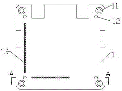
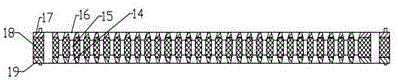
[0018] see Figure 1 to Figure 2 , the embodiment of the present invention includes:

[0019] A general-purpose test carrier board that solves the problem of high mismeasurement rate caused by glue bending, including a board body 1, T-shaped stepped holes 11 are arranged at the four corners of the board body, and the inner side of the T-shaped stepped hole 11 Both are provided with circular holes 12 , the T-shaped stepped holes 11 are used for fixing the plate body 1 , and the circular holes 12 are arranged along th...


PUM


Abstract

The invention discloses a universal test supporting plate for solving the problem of high false test rate caused by pin bending. The supporting plate comprises a plate body. The four corners of the plate body are each provided with a T-shaped stepped hole. A circular hole is formed in the inner side of each T-shaped stepped hole. The left end and the lower end of the upper plane of the plate body are each provided with a plurality of pin holes. Each pin hole sequentially comprises a bottom conical hole body, a straight hole body and an upper conical hole body from bottom to top, wherein the small-diameter end of the bottom conical hole body and the small-diameter end of the upper conical hole body are connected with the two ends of the straight hole body in a fillet mode respectively, the large-diameter end of the bottom conical hole body and the bottom plane of the plate body are located on the same horizontal plane, and the large-diameter end of the upper conical hole body and the upper plane of the plate body are located on the same horizontal plane. In this way, the universal test supporting plate for solving the problem of high false test rate caused by pin bending has the advantages of being high in strength and light in weight; manual pin pulling operation of operators is omitted, a PCBA is prevented from being scratched by the operators, the product test qualification rate is increased, and product quality is improved.

Description

technical field [0001] The invention relates to a test carrier board for an integrated circuit board, in particular to a universal test carrier board which solves the problem of high mistesting rate caused by bent pins. Background technique [0002] In the PCBA production process, because the pins of many pin-dense components are relatively thin, they are easy to bend during production. For these pin fixtures, only test pins less than 50mil can be used in the production, so the pins will bend a little bit. There is a deviation from the test needle, and even the test needle is bent, which will eventually lead to poor contact and reduce the test pass rate. [0003] In view of the above shortcomings, the main solution is to arrange personnel to straighten the bent pins with tools before testing, but this solution has the following disadvantages: the speed of manually straightening the pins is slow; it is easy to scratch the components of the PCBA; The effect of re-trimming is ...

Claims


Application Information

Patent Timeline
IPC IPC(8): G01R31/28
CPCG01R31/2863
Inventor 吴勇朱凯钟卫坚
Owner FLEXTRONICS ELECTRONICS TECH SUZHOU
Why Eureka
Try Eureka