
Gate driving device, driving method and display panel

A gate driving and driving method technology, applied in the display field, can solve the problem of high power consumption of the gate driver and the like

Active Publication Date: 2016-11-23
CHENGDU VISTAR OPTEOLECTRONICS CO LTD
View PDF7 Cites 13 Cited by
  • Summary
  • Abstract
  • Description
  • Claims
  • Application Information

AI Technical Summary

Problems solved by technology

[0008] In view of this, an embodiment of the present invention provides a gate driving device, a driving method, and a display panel, which are used to solve the problem of relatively large power consumption of the gate driver in the prior art

Method used


Image

  • Gate driving device, driving method and display panel
  • Gate driving device, driving method and display panel
  • Gate driving device, driving method and display panel

Examples


Embodiment Construction

[0031] In practical applications, after the host controller receives the image to be displayed, it converts the digital signal corresponding to the image to be displayed into an analog signal and sends it to the timing controller. The source driving device sends timing control signals, so that the gate driving device sequentially drives the shift registers step by step according to the received timing control signals, so that the shift registers output scanning signals sequentially through the gate lines, and drive the pixel units corresponding to the shift registers The gate of the TFT in the TFT is turned on; the source drive device drives the source drive circuit according to the timing control signal to apply voltage to the TFT with the gate turned on, so that the pixel unit corresponding to the TFT emits light, thereby achieving the purpose of displaying images . However, it is found through research that driving the pixel units in the pixel array to emit light step by st...


PUM


Abstract

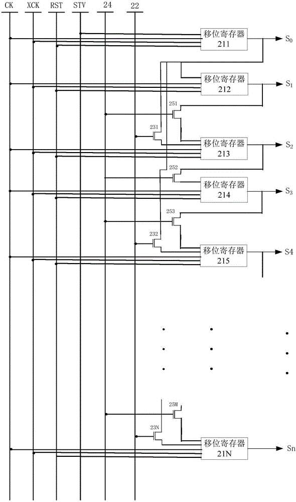
The invention discloses a gate driving device, a driving method and a display panel. The gate driving device comprises a plurality of shift registers, a first driving switch and first thin film transistors, wherein the output ends of scanning signals of first shift registers are connected with the drain electrode of at least one first thin film transistor, the input ends of scanning signals of second shift registers are connected with the source electrodes of the first thin film transistors, and the grid electrodes of the first thin film transistors are connected with the first driving switch; when the first driving switch is started to work, the second shift registers receive the scanning signals sent by the first shift registers, when the second shift registers receive the scanning signals, at least one third shift register synchronously receives the scanning signals sent by the first shift registers, so that first-level shift registers synchronously drive at least two-level shift registers to ensure the need of image display and further lower the power consumption of the device for images with lower resolutions.

Description

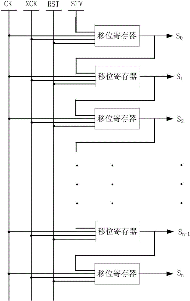
technical field [0001] The present invention relates to the field of display technology, in particular to a gate driving device, a driving method and a display panel. Background technique [0002] The thin film transistor display panel is an active matrix display panel, and the driving circuit of the thin film transistor display panel includes a host controller, a timing controller, a source driver, a gate driver, and a pixel array including a plurality of pixel units. Wherein, each pixel unit includes a thin film transistor, and the thin film transistor includes a gate, a source and a drain. [0003] Specifically, in a thin film transistor display panel, a timing driver is used to provide control signals to a source driver and a gate driver. [0004] Current gate drivers include multi-stage shift registers such as figure 2 As shown), the gate driver receives the timing control signal sent by the timing controller, and uses the timing control signal to control the operatio...

Claims


Application Information

Patent Timeline
Patent Type & Authority Applications(China)
IPC IPC(8): G09G3/20
CPCG09G3/20
Inventor 张小宝朱晖姜海斌丁立薇党鹏乐
Owner CHENGDU VISTAR OPTEOLECTRONICS CO LTD
Learn More