Seat adjusting device

a technology of seat and adjusting device, which is applied in the direction of motor/generator/converter stopper, dynamo-electric converter control, instruments, etc., can solve the problems of large amount of data to be processed, large number of different electric motors, and high cost, so as to reduce the rotation speed, reduce the scanning frequency, and reduce the rotation speed

Active Publication Date: 2013-11-26
ADIENT US LLC
View PDF17 Cites 1 Cited by
  • Summary
  • Abstract
  • Description
  • Claims
  • Application Information

AI Technical Summary

Benefits of technology

[0010]Unlike in the previous solutions, in which the detection means are arranged in the motor and require a high scanning frequency owing to the high rotation speeds of the motor shaft, in the solution according to the invention the lower rotation speeds, owing to the reduction taking place in the gearbox, can be used. The rotation speeds, which are usually distinctly lower, lead to lower scanning frequencies, which in turn make a less high-performance evaluation electronics necessary. If, on the other hand, similarly high-performance evaluation electronics are used as hitherto, then calculating capacities for other applications are now available in the evaluation electronics. Furthermore, the disturbance behavior at low frequencies is considerably less, which in turn has a positive effect on the surrounding peripheral electronics.
[0011]In addition, the solution according to the invention makes technically less complex motors possible, which are suitable both for automobile seats without memory function and also for seats with memory function. As the detection means, in contrast to previously known solutions, are now advantageously arranged on or in the gearbox instead of on the motor, motors for seat adjusting devices with a memory function can now also be used which have no detection means for determining the rotation speed. As these motors can also be used for seats without memory function, this can be used for a standardization of the electric motors with otherwise different seat adjusting devices. The motor or respectively the drive unit can therefore be provided as a standard component, which can lead to higher numbers of units and hence to lower costs of the individual electric motors. The measure provided according to the invention of providing the evaluation electronics for the evaluation of the signals provided by the at least one detection means in whole or in part on the gearbox and not on the motor also contributes to this. Hereby, the motor is also relieved of functions and can be standardized. It is particularly advantageous here if the at least one detection means is integrated into the evaluation electronics, in particular is arranged on a shared board with the evaluation electronics.
[0013]It has proved to be advantageous if the gearbox is also provided with a control unit which is arranged on the gearbox itself. The control unit can advantageously undertake all the control functions which are necessary for carrying out movements of the respective seat. Provision can also be made that the control unit only controls the functions which are necessary for operating the respective drive of the seat adjusting device. It has proved to be advantageous here if the control unit has a board with electronic circuits, with the board being arranged on the gearbox, preferably on the gearbox housing and particularly preferably inside the housing, whereby the control unit is protected from damage and contamination. The control unit can contain both the necessary control electronics and also power electronics for the motor.

Problems solved by technology

As such direct current motors usually provide drive motions with high rotation speeds, which are not able to be used directly as an adjustment movement, a reduction takes place by means of the gearbox.
In particular with a plurality of different seats, this can lead to a large number of different electric motors, which involves high costs.
In the previously known solutions, in addition it is a disadvantage that owing to the high rotation speeds of the electric motors used hitherto, high scanning frequencies are necessary, which in turn lead to a large amount of data which are to be processed, which in turn make high-performance and expensive evaluation electronics necessary.
Furthermore, through the high frequencies, high electromagnetic loads occur, which in turn entail a high expenditure to achieve an immunity to interference in the respectively adjacent assemblies.

Method used


Image

  • Seat adjusting device
  • Seat adjusting device
  • Seat adjusting device

Examples


Embodiment Construction

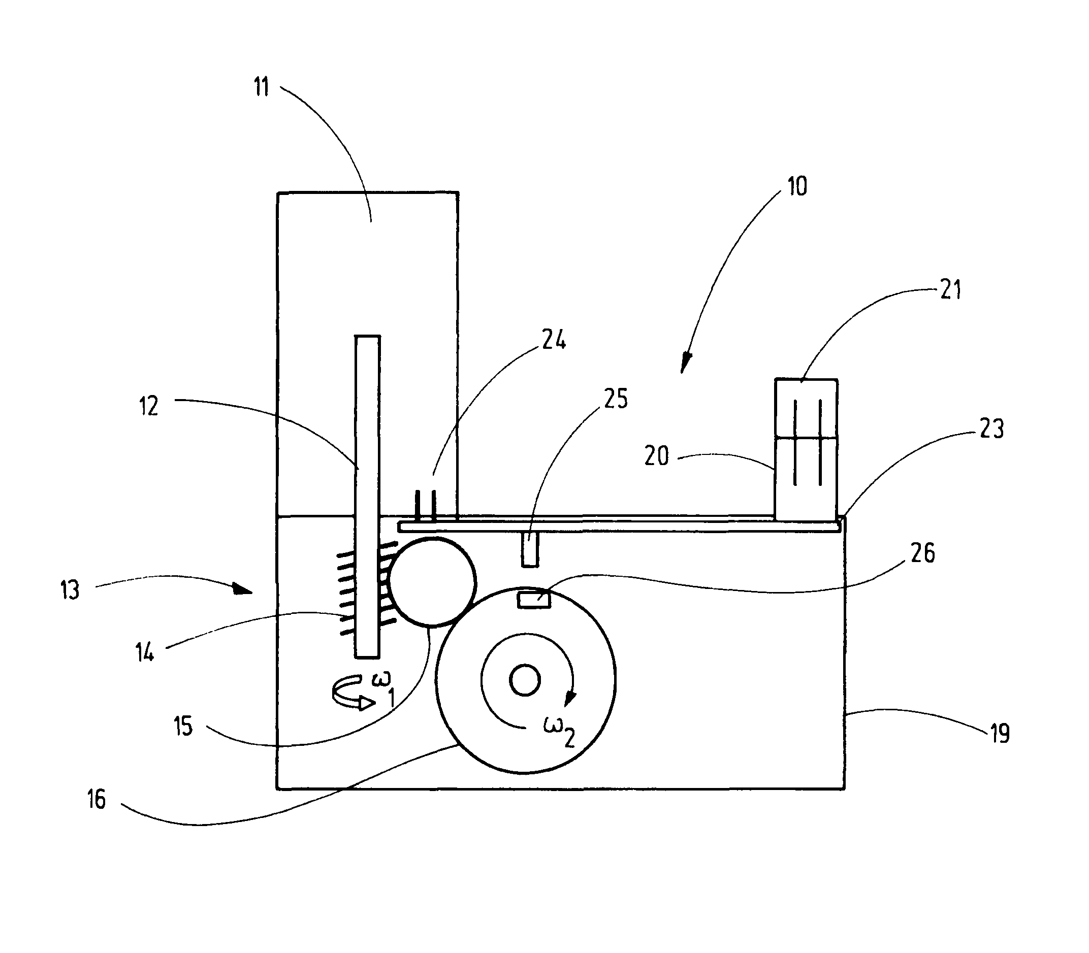
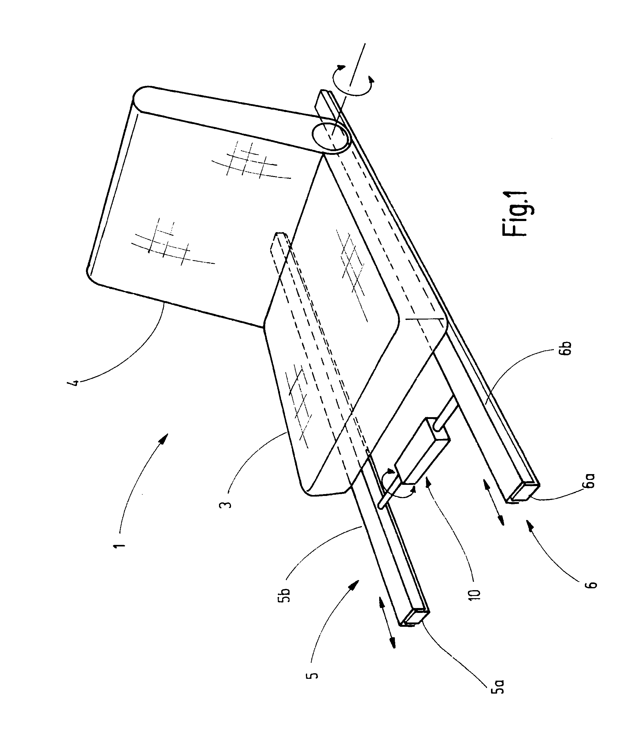
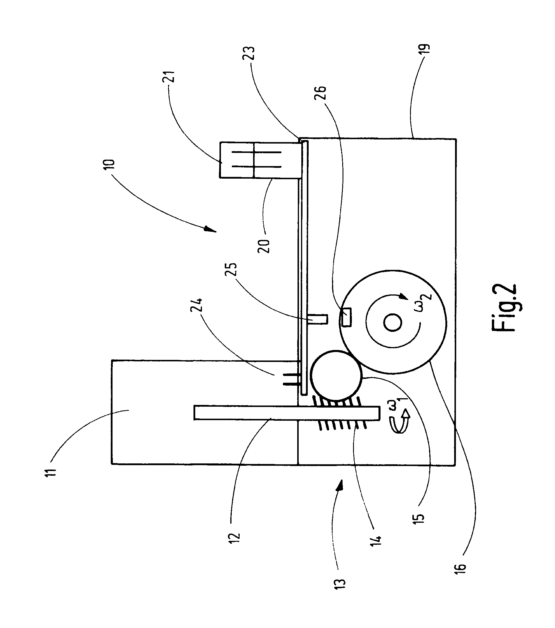
[0021]An automobile seat 1 of a motor vehicle has a seat pan part 3 and a backrest 4, which is arranged by means of two fittings laterally on the seat pan part 3, is swivelable relative thereto and is able to be locked with different inclination settings. The alignment of the automobile seat 1 in the motor vehicle and its usual travel direction on the one hand and the symmetry and arrangement of the fittings in the automobile seat 1 on the other hand define the direction indications which are used. The automobile seat is constructed as a seat with integrated seatbelt, i.e. the upper end of a safety belt is fastened to the backrest 4, more precisely to an automatic belt retraction device on the upper edge of the backrest.

[0022]For the longitudinal displacement of the seat, the latter is arranged with its seat pan part 3 on two seat track pairs 5, 6 aligned parallel to each other at a distance. Each seat track pair 5, 6 has a lower track 5a, 6a fastened on the automobile floor, and an...


PUM


Abstract

A seat adjusting device for an automobile seat (1) having an electric motor (11) for generating a drive motion, wherein the electric motor is operationally coupled to a gearbox (13) for transmitting the drive motion thereof, the gearbox having a gearbox housing (19) in which gearbox elements are disposed for a step-up or step-down transmission of the motor drive motion, by means of which electric motors of lesser technical complexity can be used than previously. To this end, the invention proposes that the gearbox (13) has detection device for detecting information about the speed of at least one of the gearbox elements or detecting a variable dependent on the speed.

Description

CROSS REFERENCE TO RELATED APPLICATIONS[0001]This application is a United States National Phase application of International Application PCT / EP2009 / 004900 and claims the benefit of priority under 35 U.S.C. §119 of German Patent Application DE 10 2008 032 162.1 filed Jul. 8, 2008, the entire contents of which are incorporated herein by reference.FIELD OF THE INVENTION[0002]The invention relates to a seat adjusting device for an automobile seat, having an electric motor for generating a drive motion, wherein the electric motor is operationally coupled to a gearbox for transmitting the drive motion thereof, said gearbox having a gearbox housing in which gearbox elements are disposed for a step-up or step-down transmission of the motor drive motion. Such a generic seat adjusting device is known from DE 10 2004 019 466 B4, the entire contents of which are incorporated herein by reference.BACKGROUND OF THE INVENTION[0003]Automobile seats, in particular single seats, are generally construc...

Claims


Application Information

Patent Timeline
Patent Type & Authority Patents(United States)
IPC IPC(8): H02P7/18H02P23/00
CPCB60N2/0232H02P23/0063B60N2/0248Y10T74/19H02P23/20B60N2/02246
Inventor DIEHL, ANDREAS
Owner ADIENT US LLC
Why Eureka
Try Eureka