Shift register unit, gate driving circuit and driving method thereof

A shift register and circuit technology, applied in static memory, digital memory information, instruments, etc., can solve the problems of increasing design difficulty and system complexity, and the influence of liquid crystal panel charging saturation, so as to reduce product cost and reduce charging The effect of reducing the scanning frequency

Active Publication Date: 2019-04-16
BOE TECH GRP CO LTD +1
View PDF6 Cites 1 Cited by
  • Summary
  • Abstract
  • Description
  • Claims
  • Application Information

AI Technical Summary

Problems solved by technology

However, the use of high-frequency drive has a great impact on the charge saturation of the LCD panel, and requires a lot of changes to the gate integrated circuit, increasing design difficulty and system complexity

Method used


Image

  • Shift register unit, gate driving circuit and driving method thereof
  • Shift register unit, gate driving circuit and driving method thereof
  • Shift register unit, gate driving circuit and driving method thereof

Examples


Embodiment Construction

[0020] The technical solutions in the embodiments of the present disclosure will be clearly and completely described below in conjunction with the accompanying drawings. Apparently, the described embodiments are only some of the embodiments of the present disclosure, not all of them. Based on the embodiments in the present disclosure, all other embodiments obtained by persons of ordinary skill in the art without making creative efforts also belong to the protection scope of the present disclosure.

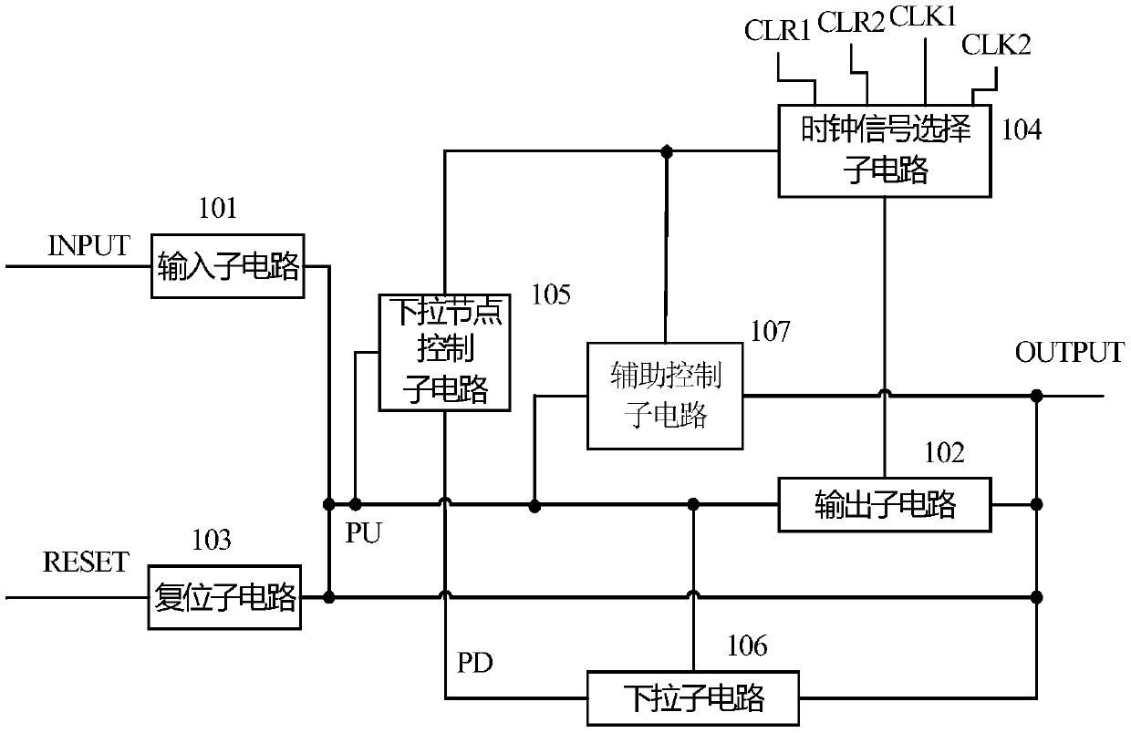
[0021] figure 1 A block diagram of a shift register unit according to an embodiment of the disclosure is illustrated. like figure 1 As shown, the shift register unit includes: an input sub-circuit 101, connected between the signal input terminal INPUT and the pull-up node PU, configured to input a signal to the pull-up node; an output sub-circuit 102, connected between the pull-up node PU and the signal Between the output terminals OUTPUT, it is configured to output a pulse signa...


PUM


Abstract

A shift register unit and its driving method, a gate drive circuit, and an array substrate, wherein the shift register unit includes: an input subcircuit connected between a signal input terminal and a pull-up node, configured to input to the pull-up node Signal; the output subcircuit is connected between the pull-up node and the signal output terminal, and is configured to output a pulse signal to the signal output terminal under the control of the pull-up node; the reset subcircuit is connected between the reset terminal, the pull-up node and the signal output terminal. Between the signal output terminals, it is configured to reset the pull-up node and the signal output terminal under the control of the reset terminal; and a clock signal selection subcircuit, the input terminal of which is connected to the first clock signal terminal and the second clock signal terminal, The first output terminal is connected to the output sub-circuit and is configured to select whether to provide the first clock signal or the second clock signal to the output sub-circuit according to the levels of the first control terminal and the second control terminal. In this way, the display panel can be freely switched between two different display modes of 2D and 3D, and simultaneous scanning of double gate lines can be realized in 3D display.

Description

technical field [0001] The present disclosure relates to the field of display technology, in particular to a shift register unit, a gate drive circuit including a multi-stage shift register and a drive method thereof. Background technique [0002] During the display process of a liquid crystal display panel including a pixel array, a gate driving circuit is used to generate gate line voltages for driving pixels on the display panel. The gate line voltage is output through the gate drive circuit, and each pixel is scanned row by row. In recent years, with the continuous improvement of the amorphous silicon thin film technology, the gate driver circuit can be integrated on the thin film transistor array substrate to form a GOA (Gate driver On Array) to drive the gate lines. The GOA driver is used to directly make the GOA unit on the liquid crystal panel, which can simplify the process, reduce the cost, and easily realize the narrow frame. [0003] Generally, a GOA composed o...

Claims


Application Information

Patent Timeline
Patent Type & Authority Patents(China)
IPC IPC(8): G09G3/36G11C19/28
CPCG09G3/3677G11C19/28G09G2310/0286G09G2310/0267G09G2320/0252G09G2320/0209H04N13/359G11C19/287G09G3/20
Inventor 赵剑王慧
Owner BOE TECH GRP CO LTD
Why Eureka
Try Eureka