Method and system for zero position measurement of permanent magnet synchronous motor

A technology of permanent magnet synchronous motor and zero position, which is applied in the direction of electronic commutator, etc., can solve problems such as non-correspondence, angle θ deviation, and inability to obtain accurate results, etc., to achieve improved accuracy, significant improvement, and significant current waveform Effect

Active Publication Date: 2016-11-23
BYD CO LTD
View PDF4 Cites 14 Cited by
  • Summary
  • Abstract
  • Description
  • Claims
  • Application Information

AI Technical Summary

Problems solved by technology

[0008] It can be seen from the above coordinate transformation relationship that if there is a deviation in the zero position value of the motor, there will be a deviation in the value of the angle θ, which will lead to the non-correspondence of the variable control position sequence in real-time high-precision control and the inability to obtain accurate results.

Method used


Image

  • Method and system for zero position measurement of permanent magnet synchronous motor
  • Method and system for zero position measurement of permanent magnet synchronous motor
  • Method and system for zero position measurement of permanent magnet synchronous motor

Examples


Embodiment Construction

[0046] Embodiments of the present invention are described in detail below, examples of which are shown in the drawings, wherein the same or similar reference numerals denote the same or similar elements or elements having the same or similar functions throughout. The embodiments described below by referring to the figures are exemplary only for explaining the present invention and should not be construed as limiting the present invention.

[0047] In the description of the present invention, it should be understood that the terms "first" and "second" are used for description purposes only, and cannot be interpreted as indicating or implying relative importance or implicitly indicating the quantity of indicated technical features. Thus, a feature defined as "first" or "second" may explicitly or implicitly include one or more of said features. In the description of the present invention, "plurality" means two or more, unless otherwise specifically defined.

[0048] In the descr...


PUM


Abstract

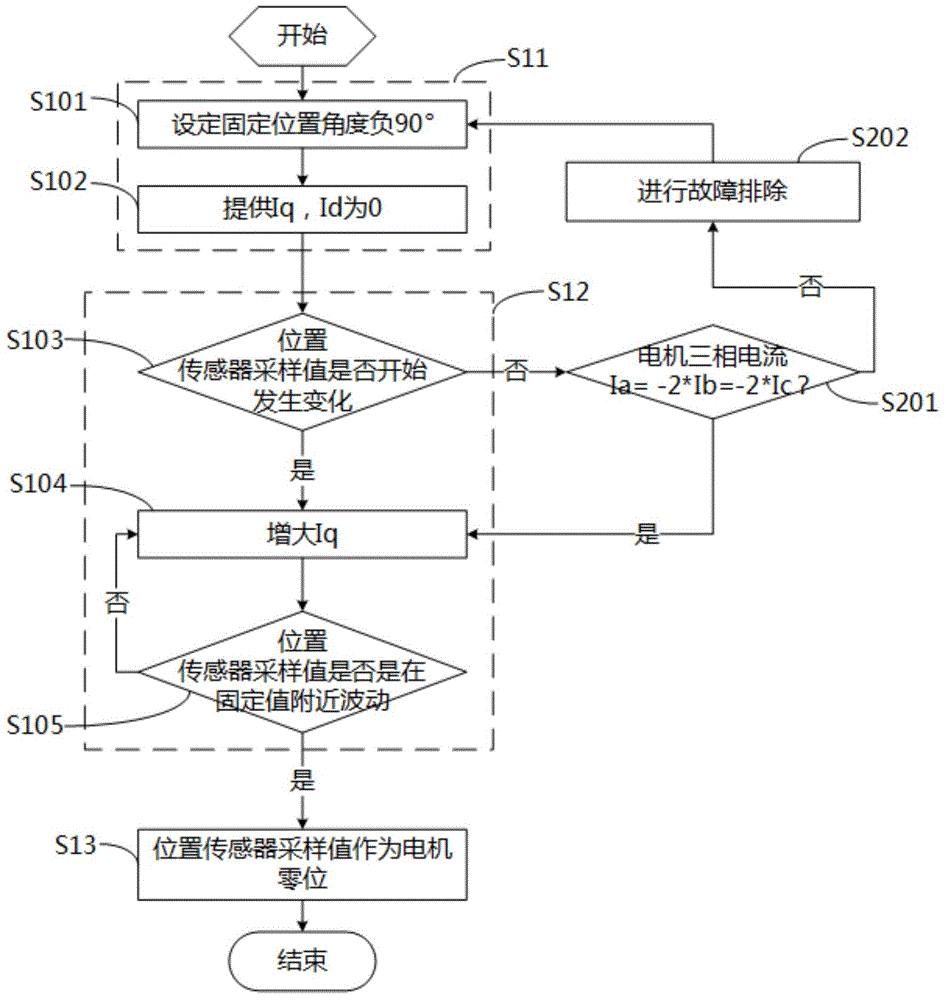
The invention discloses a method for zero position measurement of a permanent magnet synchronous motor. The method includes a static testing step and a dynamic calibration step. According to the static testing step, S11, q-axis currents are provided, and d-axis currents are set to be zero; S12, whether a sampling value of a position sensor fluctuates near a fixed value or not is judged, and if yes, the step S13 is executed; S13, the sampling value of the position sensor is used as a middle zero position. According to the dynamic calibration step, S31, the motor is dragged to rotate at set rotating speed; S32, the d-axis currents are increased, and the q-axis currents are set to be zero; S33, whether the torque of the motor is kept near zero all the time or not is judged, if yes, the step S34 is executed, and if not, the step S35 is executed; S34, the middle zero position serves as a final zero position of the motor; S35, the middle zero position is corrected, and the torque of the motor is maintained near zero. According to the method, the middle zero position is obtained after the static testing step, the middle zero position is calibrated again in the dynamic calibration step, and therefore the obtained zero position of the motor is more accurate. The invention further discloses a system for zero position measurement of the permanent magnet synchronous motor.

Description

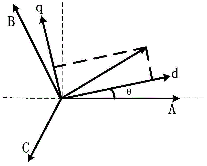
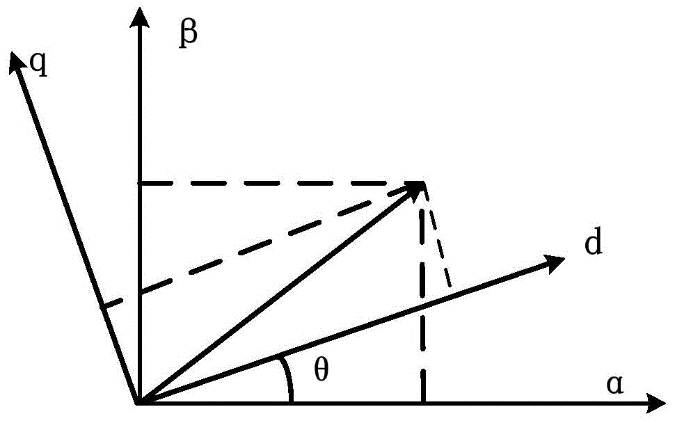
technical field [0001] 本发明涉及于电机领域,更具体而言,涉及一种用于永磁同步电机零位测量的方法及一种用于永磁同步电机零位测量的系统。 Background technique [0002] 目前,对于交流永磁电机的精确控制来说,尤其是车用永磁驱动电机的控制来说,一个重要的指标是电机扭矩的平稳、快速响应。而在控制当中,电机扭矩的平稳和快速响应是和电流有直接关系的。在现有的控制当中,电机的位置信号是一个很重要的控制变量,对控制的好坏和精度都影响很大,目前在电机上使用位置传感器来对电机的实时位置进行测量并运用到控制当中,而对于永磁同步电机来说,电机的初始位置即零位是控制当中很重要的因素,电机初始位置的准确不否直接影响到电机起动和扭矩响应性能。 [0003] 对于零位的重要性,现有的一般的方法是采用相关的与业设备如直流枪对电机三相线进行通电测试,A相通正电,B、C相通负电,通入电后,然后电机转子转到一个固定位置后不动,则这个位置就确定为电机的初始位置即零位。 [0004] 但是,上述方法中,由于每种永磁电机的磁阻扭矩及转动惯量不一样,所需要的电流不一样,故直流电流枪使用就存在缺陷了,且硬件上的不同也造成所测零位会存在偏差,从而导致电机控制上的精度较差或者导致电机的扭矩缺失或过大的情况出现。 [0005] 对于交流永磁同步电机的控制来说,零位确定之后,由位置传感器计算得到的电机角度位置信号值减去零位值得到电机的实时角度位置θ用以电机控制。现在所使用的矢量控制算法,如磁场定向控制(FOC:Field Oriented Control)算法中核心的部分是电机空间三相坐标系、两相静止坐标系和两相旋转坐标系的转换,而坐标变换中重要的变量就是角度位置θ,坐标变换的向量图(见 figure 1 :三相交流转换成两相旋转坐标变换向量图,及 figure 2 :两相旋转坐标d-q到两相静止坐标α-β的变换向量图)及变换方程(方程1:三相交流转换成两相旋转坐标变换方程;及方程2:两相旋转坐标d-q到两相静止坐标α-β的变换方程)如下: [0006] d ...

Claims


Application Information

Patent Timeline
Patent Type & Authority Applications(China)
IPC IPC(8): H02P6/16
Inventor 艾光谨肖恺杜智勇罗辉张鑫鑫
Owner BYD CO LTD
Why Eureka
Try Eureka