Eureka AIR delivers breakthrough ideas for toughest innovation challenges, trusted by R&D personnel around the world.

Direct torque control system of permanent magnet synchronous motor based on terminal sliding mode

A permanent magnet synchronous motor, direct torque control technology, applied in the control system, vector control system, motor generator control and other directions, can solve the inverter switching frequency is not constant, measurement noise, low robustness, flux linkage, etc. It can eliminate the chattering phenomenon, eliminate the uncertainty and reduce the pulsation effect.

Inactive Publication Date: 2011-04-27
CHANGCHUN UNIV OF TECH
View PDF2 Cites 56 Cited by
  • Summary
  • Abstract
  • Description
  • Claims
  • Application Information

AI Technical Summary

Problems solved by technology

[0005] In order to solve the existing technology of permanent magnet synchronous motor direct torque control system, such as flux linkage control asymmetry, large torque ripple, inverter switching frequency is not constant, robustness to system parameter perturbation, external interference, measurement noise, etc. In order to solve the problems of low stability and difficult control of flux linkage and torque at low speeds, the present invention provides a direct torque control system for permanent magnet synchronous motors based on terminal sliding mode

Method used


Image

  • Direct torque control system of permanent magnet synchronous motor based on terminal sliding mode
  • Direct torque control system of permanent magnet synchronous motor based on terminal sliding mode
  • Direct torque control system of permanent magnet synchronous motor based on terminal sliding mode

Examples


Embodiment Construction

[0017] The present invention will be described in further detail below in conjunction with the accompanying drawings.

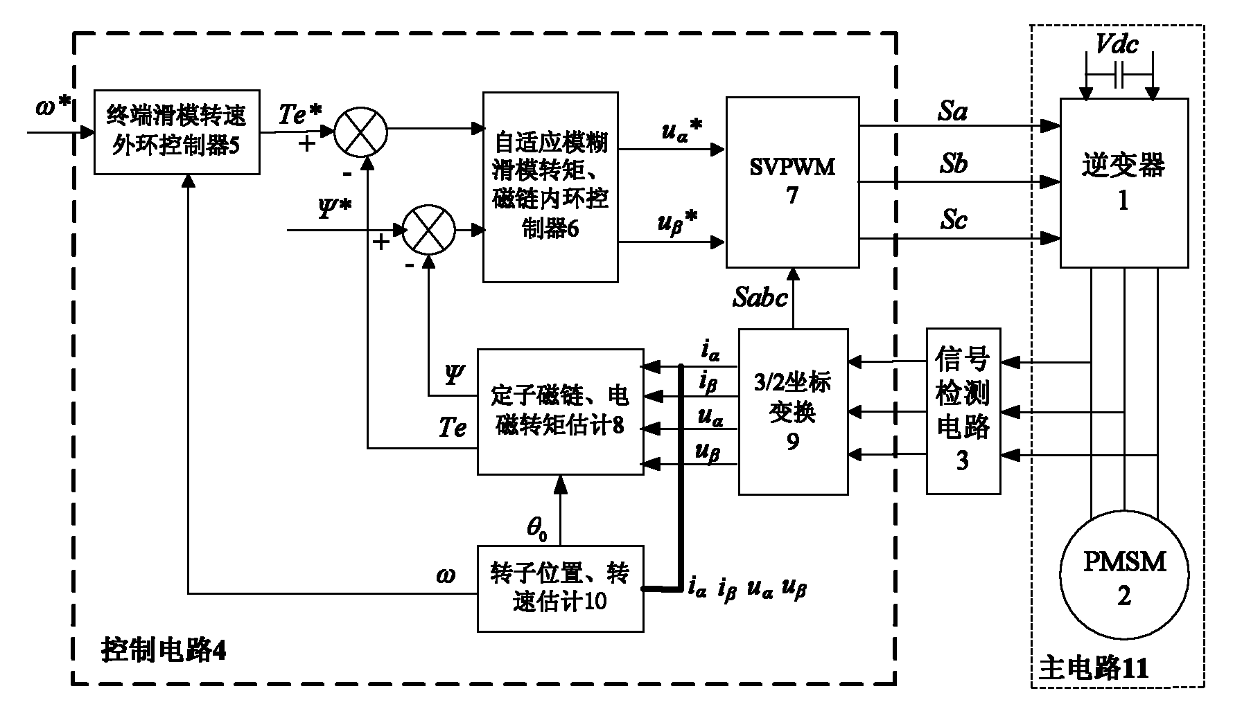
[0018] Such as figure 1 As shown, the permanent magnet synchronous motor direct torque control system based on the terminal sliding mode of the present invention includes a main circuit 11, a control circuit 4 and a signal detection circuit 3, wherein the main circuit 11 includes an inverter 1 and a PMSM module 2; the control circuit 4 Including terminal sliding mode speed outer loop controller 5, adaptive fuzzy sliding mode torque, flux linkage inner loop controller 6, SVPWM module 7, stator flux linkage, electromagnetic torque estimation module 8, 3 / 2 coordinate transformation module 9 and Rotor position, speed estimation module 10.

[0019] The specific implementation steps of the permanent magnet synchronous motor direct torque control system based on the terminal sliding mode of the present invention are as follows:

[0020] 1) The signal detection cir...


PUM


Abstract

The invention discloses a direct torque control system of a permanent magnet synchronous motor based on a terminal sliding mode, which belongs to the field of motor control. The system comprises a main circuit, a signal detection circuit, a rotational-speed outer-ring controller for the terminal sliding mode, a torque linkage inner-ring controller for an adaptive fuzzy sliding mode, a stator-linkage electromagnetic torque estimation module, an SVPWM module, a 3 / 2 coordinate transform module, and a rotor position / speed estimation module; the design on the rotational-speed outer-ring controller is realized by using a terminal sliding mode control method based on the adaptive estimation of load disturbance, and the rotational-speed outer-ring controller outputs direct-torque controlled demand signals; and the design on the torque linkage inner-ring controller is realized by using an adaptive fuzzy sliding mode control method, and the torque linkage inner-ring controller outputs two-phase alternating voltages in a two-phase stationary coordinate system; and through carrying out SVPWM transformation on the two-phase alternating voltages, a power switching element acted on an inverter of the main circuit implements the direct torque control of the permanent magnet synchronous motor. The direct torque control system in the invention has the advantages of quick torque response speed, good robustness, small tracking error, and capability of improving the reliability and static / dynamic characteristics of the system.

Description

technical field [0001] The invention belongs to the technical field of motor control, and relates to a direct torque control system of a permanent magnet synchronous motor based on a terminal sliding mode. Background technique [0002] AC permanent magnet synchronous motor (PMSM, Permanent Magnet Synchronous Machine) has the characteristics of simple structure, reliable operation, high torque-to-weight ratio, and low loss. It is widely used in high-precision and high-reliability occasions, such as industry, civil, military and other fields. The direct torque control system (DTC, Direct Torque Control) is based on the torque as the center to carry out the comprehensive control of flux linkage and torque. Different from vector control, direct torque control does not require decoupling. By detecting the stator voltage and current of the motor, the flux linkage and torque of the motor are calculated with the help of instantaneous space vector theory, and the flux linkage is rea...

Claims


Application Information

Patent Timeline
IPC IPC(8): H02P21/14H02P21/18H02P21/20H02P21/30
Inventor 张袅娜卢秀和孙颖杨宏韬王冬梅
Owner CHANGCHUN UNIV OF TECH
Why Eureka
Eureka Blog
Learn More