Automatic field-weakening method for built-in permanent magnet synchronous motor

A permanent magnet synchronous motor technology, applied in the direction of magnetic circuit rotating parts, magnetic circuit shape/style/structure, etc., can solve the problems of small effective range, increased manufacturing cost, and the inability to adjust the magnetic field of the main magnetic pole of the permanent magnet motor.

Inactive Publication Date: 2010-07-21
SHANGHAI MARITIME UNIVERSITY
View PDF0 Cites 56 Cited by
  • Summary
  • Abstract
  • Description
  • Claims
  • Application Information

AI Technical Summary

Problems solved by technology

So far, the work done by domestic and foreign scholars and engineers and technicians in this area is mainly reflected in the following four points: First, use the demagnetization effect of the unique cross-coupling effect in the permanent magnet synchronous motor to increase the power of the motor in the high-speed area Capacity, but the cross-coupling effect can be magnetization or demagnetization, depending on the rotor structure; the second is to use the flexibility of the rotor structure to set magnetic media with different properties in the rotor to increase the direct axis reactance and inductance pivot reaction, but the effective ra

Method used


Image

  • Automatic field-weakening method for built-in permanent magnet synchronous motor
  • Automatic field-weakening method for built-in permanent magnet synchronous motor
  • Automatic field-weakening method for built-in permanent magnet synchronous motor

Examples


specific Embodiment approach 1

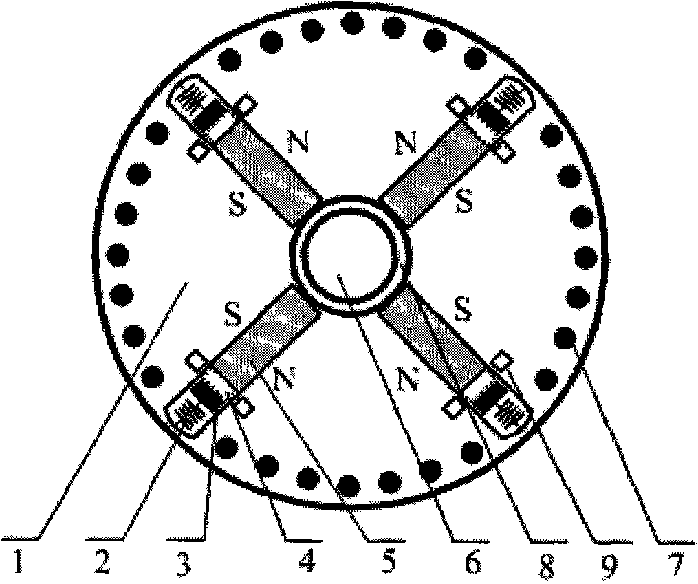
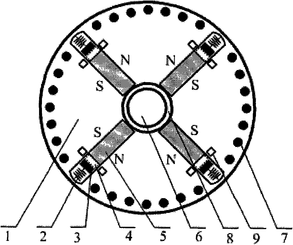
[0014] Specific implementation mode one: for figure 1 In the permanent magnet synchronous motor rotor with a four-pole tangential magnetic circuit structure shown, the rotor core 1 is made of laminated silicon steel sheets with a thickness of 0.5 mm, and evenly distributed semi-open or closed slots are punched on the inner side of the outer circumference. Four main pole magnets 5 are symmetrically built into the rotor core 1 , the magnetization direction of the magnets 5 is tangential, and two adjacent magnets together provide magnetic flux for each pole. Several rotor guide bars 7 are arranged on the inside of the outer circumference of the rotor core 1 along the direction of the direct axis. The rotor guide bars 7 are located in the rotor slots and together with the end rings form a cage-type starting winding. On the inside of the outer circumference of the rotor core 1, four chutes 4 are arranged along the direction of the orthogonal axis. Springs 2 and flux short-circuit b...

specific Embodiment approach 2

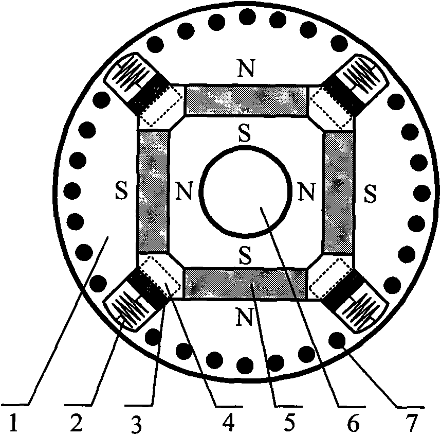
[0015] Specific implementation mode two: for figure 2 In the permanent magnet synchronous motor rotor with a four-pole radial magnetic circuit structure shown, the rotor core 1 is made of laminated silicon steel sheets with a thickness of 0.5 mm, and evenly distributed semi-open or closed slots are punched on the inner side of the outer circumference. Four main pole magnets 5 are symmetrically built into the rotor core 1 , the magnetization direction of the magnets 5 is along the radial direction, and each magnet provides magnetic flux for each pole independently. Several rotor guide bars 7 are arranged on the inside of the outer circumference of the rotor core 1 along the direction of the direct axis. The rotor guide bars 7 are located in the rotor slots and together with the end rings form a cage-type starting winding. On the inside of the outer circumference of the rotor core 1, four chutes 4 are arranged along the direction of the orthogonal axis. Springs 2 and flux short...


PUM


Abstract

The invention relates to an automatic field-weakening method for a built-in permanent magnet synchronous motor, which solves the problem that field-weakening speed is difficult to widen due to the fixed rotor excitation and small reactance of armature reaction of a direct axis in the conventional permanent magnet synchronous motor in the market. In a rotor magnetic structure of the permanent magnet synchronous motor, a magnetic flux short-circuit block is arranged in a magnetic flux isolating layer in a quadrature axis direction with the help of an automatic adjustment action of a spring; when the rotary speed of the rotor is low, the short-circuit block is positioned at a low-speed position so that interelectrode magnet leakage through the isolating layer is small; when the rotary speed of the rotor is increased, the short-circuit block gradually deviates from the low-speed position to move towards the edge of the rotor under the action of rotating centrifugal force, which expands the interelectrode magnet leakage path; and the leakage magnet flux passing through the isolating layer is increased and the main magnet flux is reduced so that the aim of automatic filed-weakening widening speed is fulfilled in the motor body and a larger speed-adjusting range is reached. The method can be applied to the permanent magnet motors which have uncertain pole numbers and tangential or radial magnet structures.

Description

technical field [0001] The invention belongs to the technical field of electromagnetic devices, and mainly relates to a rotor magnetic circuit of a permanent magnet synchronous motor. Background technique [0002] In modern motion control systems, permanent magnet synchronous motors are favored by people for their outstanding advantages. The main advantages of permanent magnet synchronous motors are high efficiency and energy saving, simple structure and flexibility. However, the permanent magnet synchronous motor also has the disadvantage that the main pole flux cannot be directly adjusted. In the AC speed control system, when the speed rises to a certain range, it is necessary to adopt a constant power operation mode, which requires reducing the excitation flux and operating in a field-weakening mode. The usual solution is to increase the direct-axis armature current and use the inherent armature reaction of the motor to weaken the main pole flux, but this will increase ...

Claims


Application Information

Patent Timeline
IPC IPC(8): H02K1/27
Inventor 谢卫赵冰洁
Owner SHANGHAI MARITIME UNIVERSITY
Why Eureka
Try Eureka