Plate fixing method and printing machine for implement same

A printing machine and printing plate technology, which is applied in the direction of printing machine, rotary printing machine, general parts of printing machinery, etc.

Active Publication Date: 2016-11-30
海德堡印刷机械知识产权股份两合公司
View PDF11 Cites 3 Cited by
  • Summary
  • Abstract
  • Description
  • Claims
  • Application Information

AI Technical Summary

Problems solved by technology

Since the printing plate rests on the stop under its weight, when the guide element is swung into the operating position, there a

Method used


Image

  • Plate fixing method and printing machine for implement same
  • Plate fixing method and printing machine for implement same
  • Plate fixing method and printing machine for implement same

Examples


Embodiment Construction

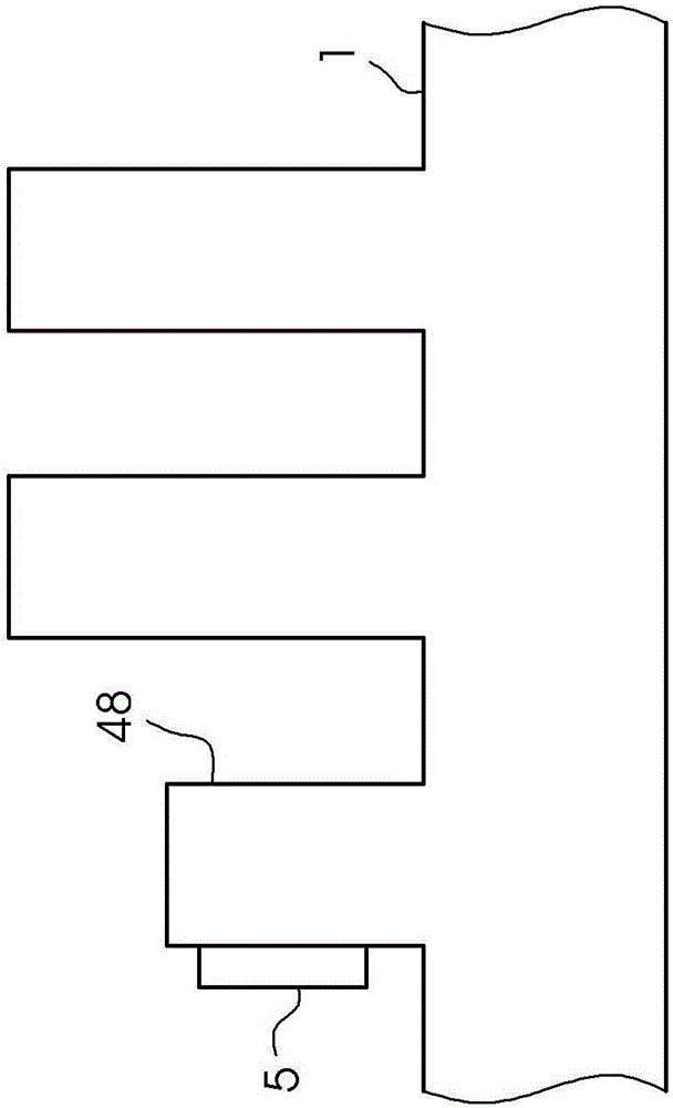
[0028] figure 1 A printing press 1 is shown which has an offset printing unit and a flexographic printing unit as varnishing unit 48 . The printing press is a sheet printing press with a feeder and a delivery not shown.

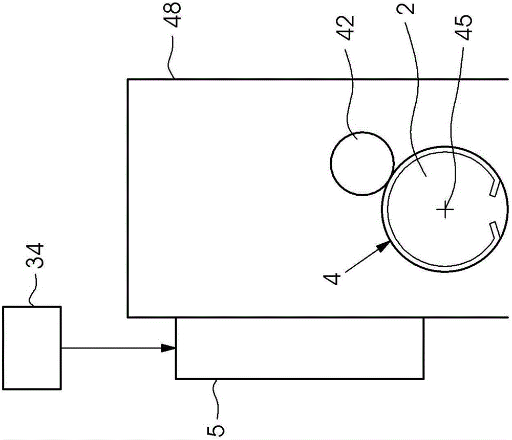
[0029] figure 2 It is shown that the coating unit 48 has the plate cylinder 2 and has the plate changer 5 for changing the printing plates 4 . Plate 4 is a flexographic plate for spot varnish. During printing operation, a roller 42 , which is both an application roller and an anilox roller, rolls on the printing plate 4 .

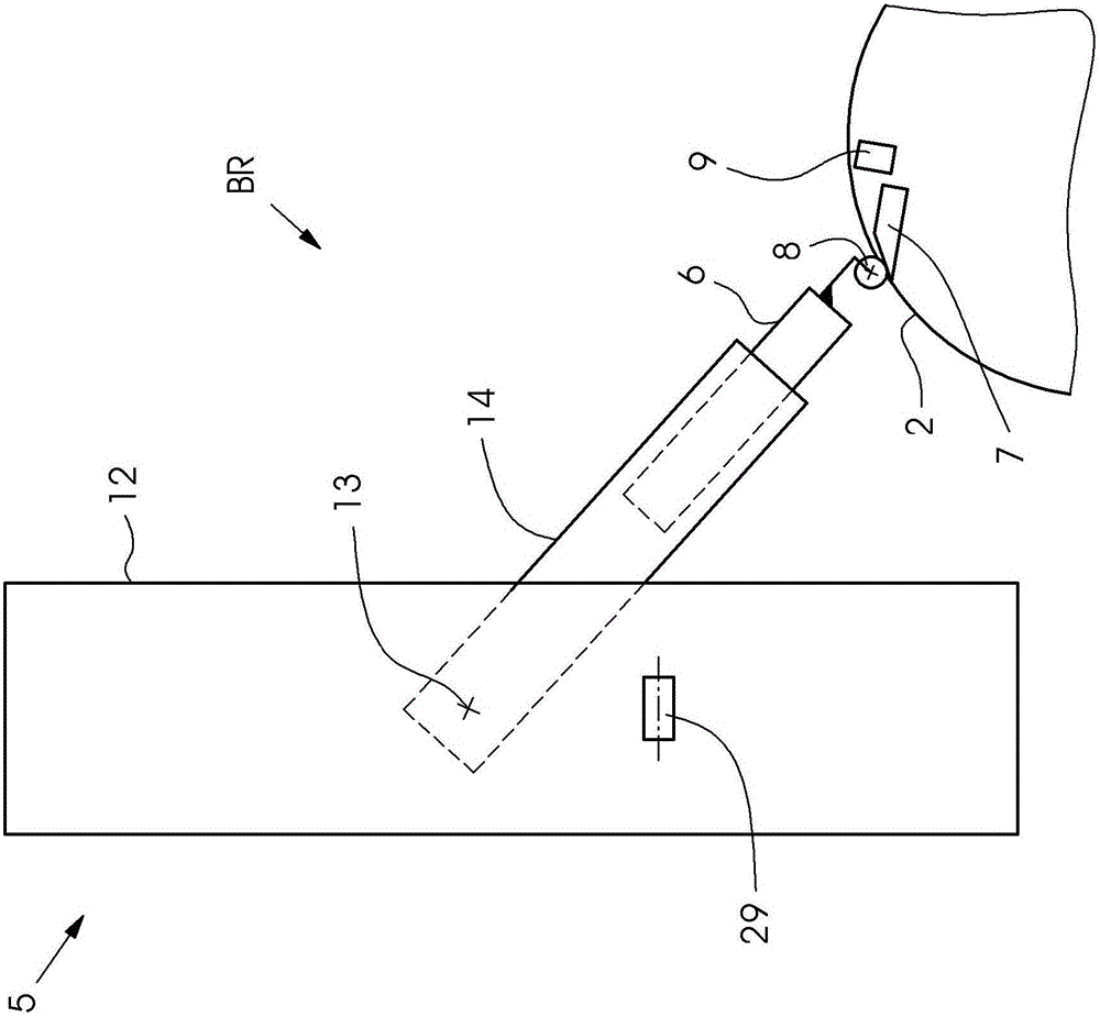
[0030] image 3 It is shown that the plate changer 5 has a plate guide 14 and a plate well 12 which extends vertically. The plate guide 14 is mounted in the hinge 13 and is foldable. The transport slide 6 is mounted displaceably in a printing plate guide 14 . The printing plate guide 14 is pivoted about the hinge 13 in order to adjust the printing plate guide 14 into the feeding position 46 (see FIG. 4 ). The printing plate guide ...


PUM


Abstract

A method for fixing a plate (4) to a plate cylinder of a printing machine by means of a plate changer comprises several steps: in a first step, register punches (28) which are introduced into the plate (4) are placed over first register pins (29) which are attached to a plate chute of the plate changer. In a second step, the plate (4) is fixed firmly via a holding device (17) which is fixed to a conveying slide block. In a third step, the conveying slide block together with the fixed plate (4) is moved away from the first register pins (29) in a first direction (31), and free spaces (33) between the register punches (28) and the first register pins (29) are produced.

Description

technical field [0001] The invention relates to a method for fastening a printing plate on a plate cylinder of a printing press by means of a plate changer and to a printing press with a plate cylinder and a plate changer for carrying out the method. Background technique [0002] Document EP 1 138 486 A2 describes a printing press with a printing plate cassette in which printing plates are prepositioned by means of a pre-coupling pin system. The printing plates are released from the cassette for plate replacement by means of the pre-mating pins being pulled back. [0003] Document DE 10 2009 012 147 A1 describes a printing plate supply device having a guide element for a printing plate. The guide element is pivotable from a receiving position for the printing forme into an operating position for feeding the printing forme. The printing plate has in its front edge two receptacles which are brought into contact with the printing plate supply for prepositioning the printing p...

Claims


Application Information

Patent Timeline
IPC IPC(8): B41F13/12B41F27/12B41F33/16
CPCB41F13/12B41F27/1218B41F33/16B41F27/06B41F27/12B41F27/1225
Inventor S·巴莱斯M·祖贝尔D·舍恩曼M·格赖弗G·斯特凡B·西茨曼
Owner 海德堡印刷机械知识产权股份两合公司
Why Eureka
Try Eureka