Combined flue gas washing tank

A washing tank and combined technology, which is applied to combined devices, gas treatment, dispersed particle separation, etc., can solve the problems of low utilization rate of washing liquid, flue gas emission, and consumption of large washing liquid, and increase the initial investment and maintenance cost. , Guarantee the discharge standard, improve the effect of utilization

Inactive Publication Date: 2016-12-07
ANHUI TIAN CHENG KE AUTOMATION TECH CO LTD
View PDF6 Cites 4 Cited by
  • Summary
  • Abstract
  • Description
  • Claims
  • Application Information

AI Technical Summary

Problems solved by technology

At present, most of the flue gas washing devices adopt the washing and dust removal device of direct spraying, the effect is not good, and the removal rate of dust in the flue gas is low; although there are flue gas washing equipment using washing liquid in the prior art, the equipment costs a lot , it is impossible to change the washing capacity of the equipment according to the actual situation, and the utilization rate of the washing liquid inside the equipment is low, and it takes a lot of washing liquid to wash the flue gas
In addition, the flue gas washing equipment in the prior art needs to replace the washing liquid in time after the washing liquid is saturated with impurities. in the atmosphere

Method used


Image

  • Combined flue gas washing tank
  • Combined flue gas washing tank

Examples


Embodiment Construction

[0013] The present invention will be further explained below in conjunction with specific embodiments.

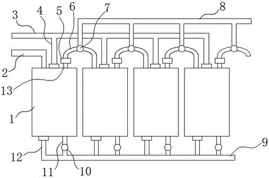
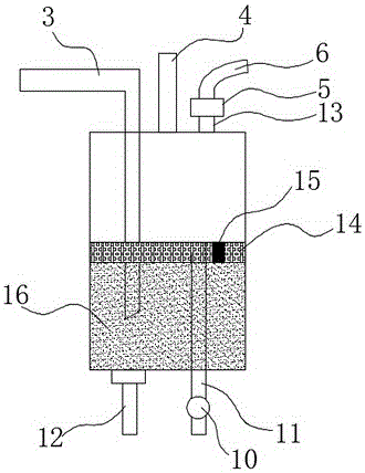
[0014] A combined flue gas washing tank proposed by the present invention includes a plurality of washing tank bodies 1 arranged side by side. The upper end of the washing tank body 1 is provided with an air inlet pipe 2, a liquid feeding pipe 4 and an air outlet pipe 13. The washing tank body 1 The lower end of the washing tank body 1 is provided with a drain pipe 12 and an overflow pipe 11, and the top of the washing tank body 1 is provided with a liquid filling pipe 3. A gas outlet main pipe 8 is provided, and the gas outlet pipe 13 of the washing tank body 1 communicates with the inlet pipe 2 of a washing tank body 1 adjacent to it through the connecting pipe 6, and one end of the connecting pipe 6 is connected to a washing tank body 1 through a first sleeve joint. The outlet pipe 13 is connected, and the other end of the connecting pipe 6 is connected to the inlet pipe...


PUM


Abstract

The invention discloses a combined flue gas washing tank which comprises multiple washing tank bodies arranged in parallel. A gas inlet pipe, a liquid adding pipe and a gas outlet pipe are arranged at the upper end of each washing tank body, a liquid discharging pipe and an overflow pipe are arranged at the lower end of each washing tank body, a main liquid adding pipe is arranged above each washing tank body, liquid adding pipes of the washing tank bodies are communicated with the main liquid adding pipe, a main gas outlet pipe is arranged on the main liquid adding pipe, the gas outlet pipes of the washing tank bodies are communicated with the gas inlet pipe of one washing tank body adjacent to each washing tank body through a connecting pipe, flue gas detection devices are arranged on the gas outlet pipes, electromagnetic three-way valves are arranged on the connecting pipes, reversing ports of the electromagnetic three-way valves are communicated with the main gas outlet pipe through conduits, and a main liquid discharging pipe is arranged under the washing tank bodies. The combined flue gas washing tank can ensure that washed flue gas can reach the discharge standard. In addition, a multi-stage washing mode is adopted, flue gas discharge reaching the standard can be still ensured under the situation that replacement is not performed in time after impurities in washing liquid in each single washing tank body are saturated.

Description

technical field [0001] The invention relates to a flue gas washing device, in particular to a combined flue gas washing tank. Background technique [0002] Industrial production processes and environmental protection emissions often require pretreatment of various gases to be analyzed. Water washing is a relatively common method for removing coke and impurities. At present, most of the flue gas washing devices adopt the washing and dust removal device of direct spraying, the effect is not good, and the removal rate of dust in the flue gas is low; although there are flue gas washing equipment using washing liquid in the prior art, the equipment costs a lot , It is impossible to change the washing capacity of the equipment according to the actual situation, and the utilization rate of the washing liquid inside the equipment is low, and it takes a lot of washing liquid to wash the flue gas. In addition, the flue gas washing equipment in the prior art needs to replace the washi...

Claims


Application Information

Patent Timeline
Patent Type & Authority Applications(China)
IPC IPC(8): B01D47/02B01D50/00
CPCB01D47/02B01D2258/0283B01D50/60
Inventor 刘秀柏王洋
Owner ANHUI TIAN CHENG KE AUTOMATION TECH CO LTD
Why Eureka
Try Eureka