Shearing device for iron core

A shearing device and iron core technology, which is applied in the direction of shearing device, nibbling cutting device, and accessory device of shearing machine, etc. It can solve the problems of inability to adjust the iron core, difficulty in controlling the length of the iron core, and the production of the iron core. The equipment is not ideal enough to achieve the effect of compact structure connection and long service life

Inactive Publication Date: 2016-12-07
CHANGSHU ZHONGYING ELECTRONICS
View PDF7 Cites 0 Cited by
  • Summary
  • Abstract
  • Description
  • Claims
  • Application Information

AI Technical Summary

Problems solved by technology

[0003] The existing iron core production equipment of some magnets is not ideal, the length of the iron core is not easy to control, and the length of the ir

Method used


Image

  • Shearing device for iron core
  • Shearing device for iron core

Examples


Example Embodiment

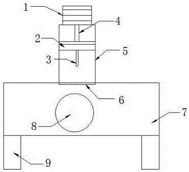
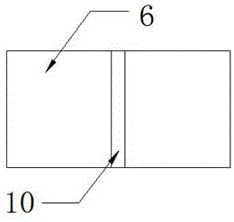
[0018] Example: such as Figure 1-2 As shown, a shearing device for an iron core includes a drive motor 1, a connecting plate 2, a cutting knife 3, a telescopic rod 4, a support base 5, a cutting board 6, a frame 7, a rotating shaft 8, a supporting foot 9 and a cutting Slot 10; the top of the frame 7 is equipped with a support base 5, the top of the support base 5 is provided with a driving motor 1, and a telescopic rod 4 is provided under the driving motor 1, and the bottom end of the telescopic rod 4 is connected with a connecting plate 2, a connecting plate 2 is equipped with a cutting knife 3 at the bottom end, four feet 9 are installed at the bottom end of the frame 7, a rotating shaft 8 is arranged inside the frame 7, a cutting board 6 is arranged on the surface of the frame 7, and the middle of the cutting board 6 A cutting groove 10 is provided.

[0019] As a technical optimization solution of the present invention, the rotating shaft 8 and the frame 7 are connected in r...


PUM


Abstract

The invention provides a shearing device for an iron core. The shearing device comprises a driving motor, a connecting plate, a cutting knife, an extensible rod, a supporting base, a cutting board, a rack, a rotating shaft, supporting legs and a cutting groove. The supporting base is installed at the top end of the rack. The driving motor is arranged at the top end of the supporting base. The extensible rod is arranged beneath the driving motor. The bottom end of the extensible rod is connected with the connecting plate. The cutting knife is installed at the bottom end of the connecting plate. The four supporting legs are installed at the bottom end of the rack. The rotating shaft is arranged inside the rack. The cutting board is arranged on the surface of the rack, and the cutting groove is formed in the middle of the cutting board. The shearing device can be used for machining the iron core of a soft magnet directly, structural connection is compact, and the service life is long. The length of the cut iron core can be adjusted as required, and using is convenient and easy. The supporting base can support a power source in the cutting process, so that the function of stable operation is achieved, the driving motor can drive equipment to move slowly, and the iron core can be cut.

Description

technical field [0001] The invention relates to a cutting device, in particular to a shearing device for iron cores. Background technique [0002] The iron core of the soft magnet is used inside the power equipment, and the iron core can effectively provide components for the operation of the power equipment, and the application range of the iron core is relatively wide. The outer surface of the iron core needs to be polished during the production process, and the polished iron core is more convenient to use. The iron core needs to use cutting equipment during the production process. The iron core can be cut according to the needs when cutting, and it is more convenient to use after cutting. [0003] The existing iron core production equipment of some magnets is not ideal, the length of the iron core is not easy to control, and the length of the iron core cannot be adjusted in time according to the needs. Therefore, in view of the above problems, a method for iron core is p...

Claims


Application Information

Patent Timeline
IPC IPC(8): B23D27/04B23D33/02
CPCB23D27/04B23D33/02
Inventor 常国青
Owner CHANGSHU ZHONGYING ELECTRONICS
Why Eureka
Try Eureka