Welding jig suitable for buckling pipe fittings

A technology for welding fixtures and bending pipes, applied in the field of pipe fitting welding and machining, can solve the problems of large space occupation, high cost, long time consumption, etc., and achieve the effect of saving overhead and cost, ensuring welding accuracy, and reducing welding time consumption.

Inactive Publication Date: 2016-12-07
GUIZHOU ZUNYI CHI YU PRECISION MACHINERY MFG
View PDF8 Cites 4 Cited by
  • Summary
  • Abstract
  • Description
  • Claims
  • Application Information

AI Technical Summary

Problems solved by technology

[0003] The purpose of the present invention is to provide a welding fixture suitable for bending pipe fittings to solve the problems of long time consumption, low efficiency, easy bending or deviation of pipe fittings, large errors, and low qualified rate of finished products in the existing bending pipe fittings. , high cost and large space occupation

Method used


Image

  • Welding jig suitable for buckling pipe fittings
  • Welding jig suitable for buckling pipe fittings
  • Welding jig suitable for buckling pipe fittings

Examples


Embodiment 1

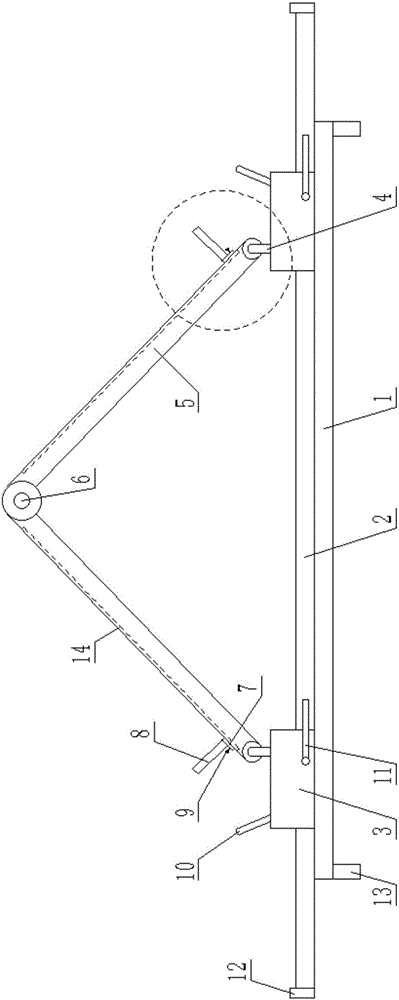
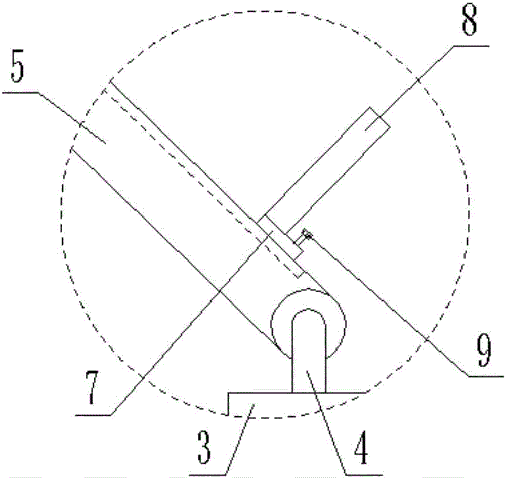
[0023] Example 1: When it is necessary to weld a 90° bent pipe fitting and the lengths of the two pipe bodies 15 are different, the slide seat 3 is pushed or pulled by the handle 10 to slide on the slide rail 2, so that a 90° clip is formed between the two support plates 5 Angle, after the position is adjusted, fix the two sliding seats 3 on the slide rail 2 by rotating the lock 11 to avoid secondary sliding. At this time, place the two pipe bodies 15 to be welded on the support plate 5, loose The locking screw 9 pushes the slider 7 to slide on the chute 14, the lower end of the pipe body is against the baffle plate 8, and the two sliders 7 are pushed at the same time so that the two pipe bodies 15 on both sides are close to each other and spliced ​​together, and then reassembled Tighten the locking screw to fix the slider 7, image 3 In the state shown, tailor welding of the pipe body 15 can be carried out, and the finished product is a bent pipe fitting with an included angl...

Embodiment 2

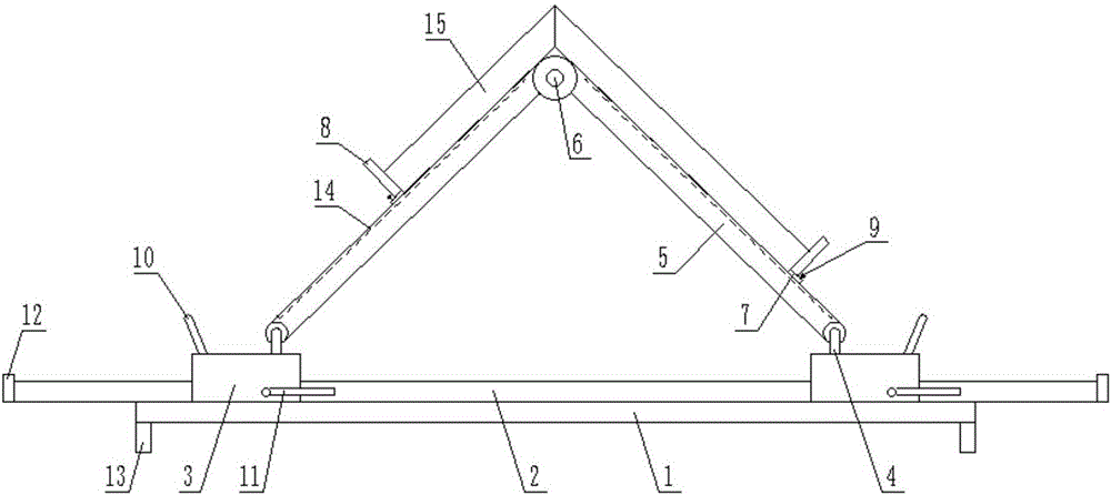
[0024] Example 2: When it is necessary to weld a 120° bending pipe fitting, push or pull the slide seat 3 to slide on the slide rail 2 through the handle 10, so that a 120° included angle is formed between the two support plates 5, and the position is adjusted by rotating The lock 11 fixes the two sliding seats 3 on the slide rail 2 to avoid secondary sliding. At this time, place the two pipe bodies 15 to be welded on the support plate 5, and loosen the locking screw 9 to push the slider 7 Sliding on the chute 14, the lower end of the pipe body is against the baffle plate 8, and at the same time push the two sliders 7 so that the two pipe bodies 15 on both sides are close to each other and spliced ​​together, and then re-tighten the locking screw to lock the slider 7 fixed Figure 4 In the state shown, tailor welding of the pipe body 15 can be carried out, and the finished product is a bent pipe fitting with an included angle of 120°.


PUM


Abstract

The invention discloses a welding fixture suitable for bending pipe fittings, which comprises a base, a slide rail is fixedly connected to the top of the base, two sliding seats are slidably installed on the slide rail, and a vertically arranged clamp is fixed on the top of each sliding seat. A hinged rod, each hinged rod is hinged with a support plate, the ends of the two support plates are hinged through a hinge seat, and a rotary lock is installed at the front end of the slide seat. The invention realizes angle adjustment through two sliding seats and two support plates hinged to each other, and then realizes the welding requirements of pipe fittings with different angles; and realizes the welding requirements of pipe fittings of different lengths through the sliders on the support plates, and further solves the problem. The traditional welding jig cannot adjust the angle and length.

Description

technical field [0001] The invention relates to the technical field of mechanical processing, in particular to the technical field of pipe fitting welding, in particular to a welding fixture suitable for bending pipe fittings. Background technique [0002] At present, in the field of welding, it is often necessary to weld bent pipes, that is, to splice two pipes together to form a specific angle between them, and then weld the two independent pipes into a whole by welding at the joint position of the two pipes For bent pipe fittings, the traditional welding method is mainly done manually, that is, the staff will splice the two pipe fittings to be welded together and clamp them with a simple fixture. The fixture is generally horizontally fixed, that is, the pipe fittings are horizontal Placed, after welding one side, you need to take out the pipe fittings and turn over to weld the other side. Obviously, the traditional welding method is not only time-consuming and inefficient...

Claims


Application Information

Patent Timeline
Patent Type & Authority Applications(China)
IPC IPC(8): B23K37/053
CPCB23K37/0533
Inventor 邱怀鸣方建平
Owner GUIZHOU ZUNYI CHI YU PRECISION MACHINERY MFG
Why Eureka
Try Eureka