

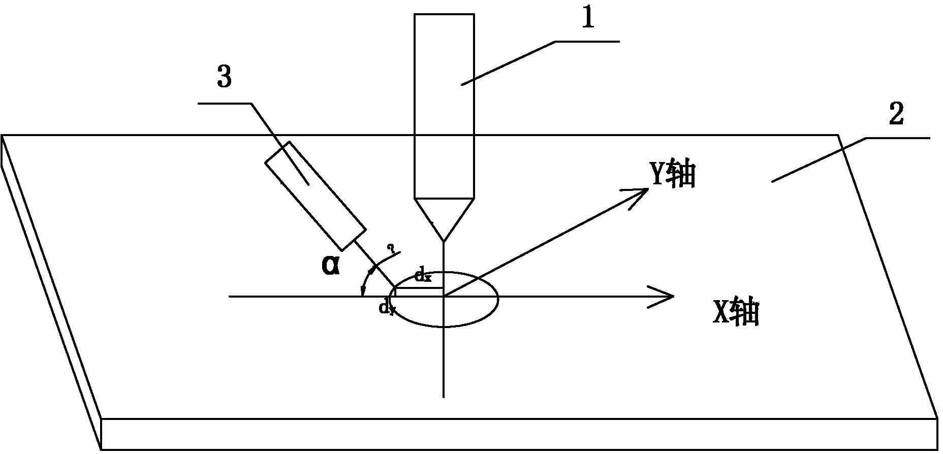
Wire side feeding clamping mechanism for welding
A technology of support mechanism and wire feeding, which is applied in welding equipment, plasma welding equipment, characteristics of welding rods, etc., can solve the problems that the angle and position of wire feeding cannot be adjusted in real time, the welding wire cannot be transitioned, and the wire feeding resistance is large, so as to avoid welding seams. The effect of quality degradation
- Summary
- Abstract
- Description
- Claims
- Application Information
AI Technical Summary
Problems solved by technology
Method used
Image

Examples
Embodiment Construction
[0015] The present invention will be further described in detail below in combination with specific embodiments.
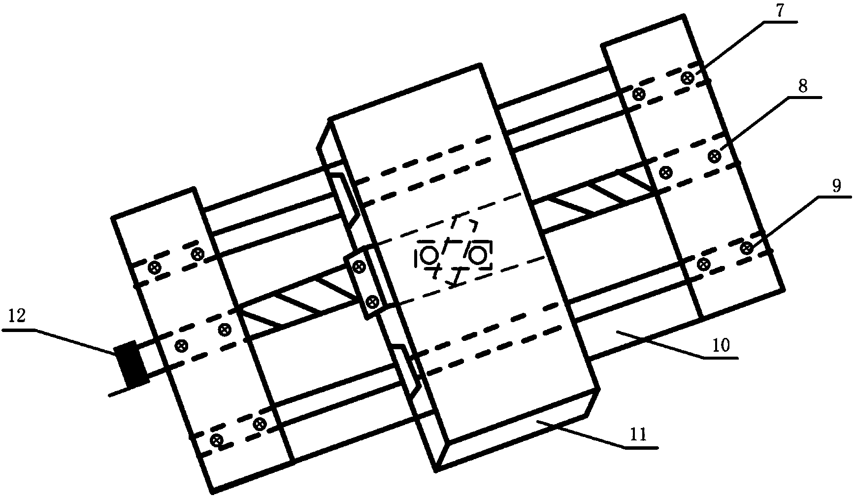
[0016] Such as Figure 5 As shown, the present invention is a welding side wire feeding clamping mechanism, including a wire feeding guide 3, a welding torch holder 5, a cross sliding device 6 and a wire feeding angle adjustment structure, the cross sliding device 6 and the welding torch holder 5, the wire feeding angle adjustment structure is connected to the wire feeding guide 3 and the cross sliding device 6 respectively.
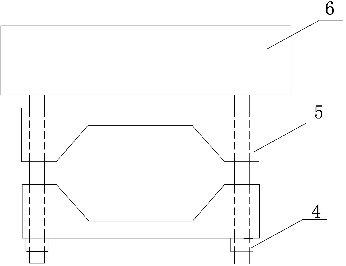
[0017] Such as figure 2 and Figure 5 As shown, the welding torch clamping body 5 is composed of two clamping blocks with V-shaped openings, and the cylindrical plasma welding torch or argon tungsten arc welding torch is held in the V-shaped openings by using bolt and nut connectors. At the same time, the bolt 4 is fixed on the On the cross sliding device 6 , the front end of the welding torch 17 is a ceramic nozzle 19 , and the front en...
PUM
| Property | Measurement | Unit |
|---|---|---|
| distance | aaaaa | aaaaa |
Abstract
Description
Claims
Application Information