Axial flexible deburring spindle

A deburring and spindle technology, applied in the field of machining and manufacturing, can solve the problems of easy damage to workpieces, tool damage, high processing costs, and achieve the effect of easy gas supply

Inactive Publication Date: 2016-12-07
侯治国
View PDF10 Cites 6 Cited by
  • Summary
  • Abstract
  • Description
  • Claims
  • Application Information

AI Technical Summary

Problems solved by technology

[0003] Existing automated mechanical deburring devices are divided into rigid deburring devices and flexible deburring devices. Among them, the rigid deburring device is characterized by simple structure and low cost, but the processing effect on workpieces with complex shapes is not good, and it is easy to damage the workpiece; in addition , due to the inconsistency of the size of the part itself and the flash size, the grinding quality is unstable and the tool is easy to be damaged
If the traditional rigid cutting method is used for grinding parts, the grinding quality cannot be guaranteed, and it will also cause problems such as short tool life and high processing costs.
[0004] Furthermore, there are also workpieces with a certain radian. This kind of workpiece has a radian problem or a certain degree of undulation during grinding. In this case, if a rigid shaft is used to process the workpiece, it may damage the original workpiece The contour changes, so that the equipment cannot reach the original design situation. In this case, a rotating shaft mechanism with a lifting effect is required, so that the workpiece contour can guide the working head to a certain extent, instead of forced grinding, resulting in workpiece contour so change

Method used


Image

  • Axial flexible deburring spindle
  • Axial flexible deburring spindle

Examples


Embodiment Construction

[0021] The technical solutions of the present invention will be further described below in conjunction with the accompanying drawings and through specific implementation methods.

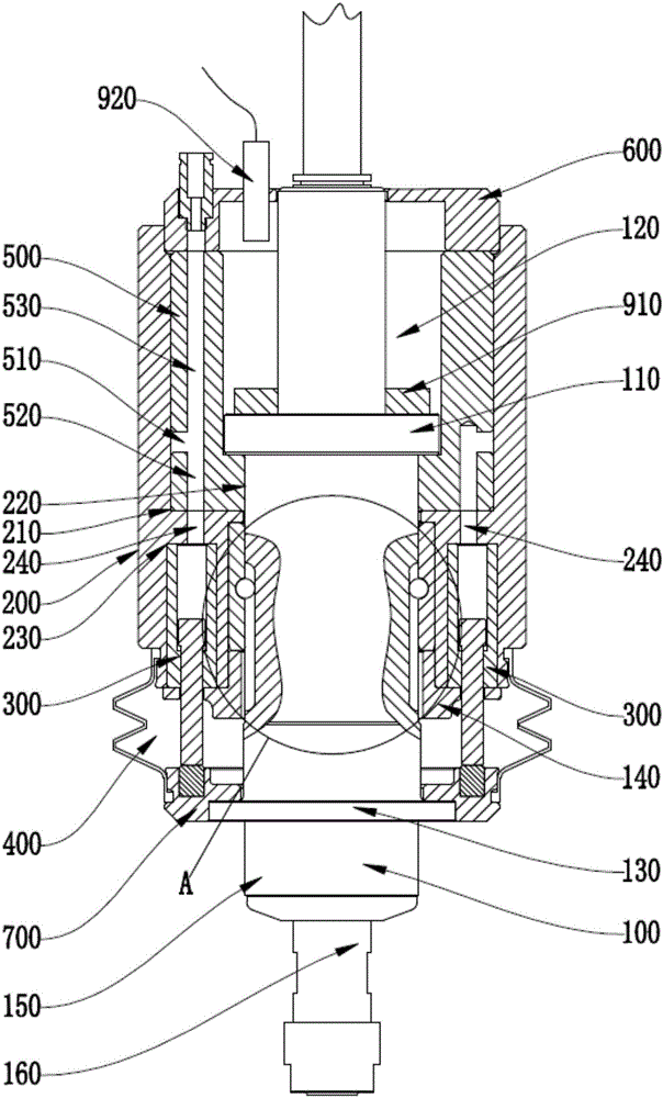
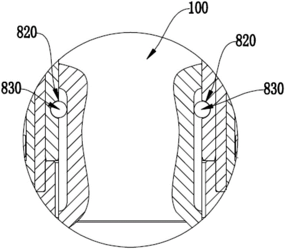
[0022] Such as Figure 1-2 As shown, it includes a main shaft 100, a casing 200, and a cylinder 300; the main shaft 100 includes an outer sliding shaft 150 and an inner working shaft 160, and the inner working shaft 160 is rotatably arranged on the outer sliding shaft 150, and the inner working shaft 160 and the outer sliding shaft 150 are rotationally matched; the main shaft 100 is installed in the main shaft installation hole 220 of the casing 200, and the main shaft 100 slides axially along the main shaft installation hole 220, and at least two of the cylinders 300 are installed in the lower end of the casing 200 in an annular array, and the cylinder 300 acts on the outer sliding shaft 150 at the same time, so that the working end of the inner working shaft 160 can play a flexible and self-adapti...


PUM


Abstract

The invention relates to the field of mechanical processing and manufacturing, in particular to an axially flexible deburring main shaft of end face deburring and grinding equipment, including a main shaft, a casing and a cylinder; the main shaft includes an outer sliding shaft and an inner working shaft, and the inner working shaft is rotatably arranged on The outer sliding shaft, the inner working shaft and the outer sliding shaft are rotationally matched; the main shaft is installed in the main shaft installation hole of the casing, and the main shaft slides axially along the main shaft installation hole, and at least two cylinders are installed at the lower end of the casing in a circular array, and the cylinders act simultaneously The outer sliding shaft makes the working end of the inner working shaft play a flexible and self-adaptive role when it contacts the workpiece. The device has a compact and reliable telescopic mechanism, the telescopic mechanism is pneumatically controlled, and the air pressure can be adjusted according to the usage conditions, so as to adjust the elasticity of the telescopic mechanism.

Description

technical field [0001] The invention relates to the field of mechanical processing and manufacturing, in particular to an axially flexible deburring spindle of end face deburring and grinding equipment. Background technique [0002] The workpieces formed at one time by die-casting or mold technology will inevitably produce burrs such as risers and flashes during the production process. In order to avoid affecting the subsequent processing and the quality of the final product, these burrs must be dealt with intensively before the subsequent processing. [0003] Existing automated mechanical deburring devices are divided into rigid deburring devices and flexible deburring devices. Among them, the rigid deburring device is characterized by simple structure and low cost, but the processing effect on workpieces with complex shapes is not good, and it is easy to damage the workpiece; in addition , Due to the inconsistency of the size of the part itself and the size of the flash, ...

Claims


Application Information

Patent Timeline
Patent Type & Authority Applications(China)
IPC IPC(8): B24B9/00B24B41/04
CPCB24B9/00B24B41/04
Inventor 侯治国王爽秦磊谭琳阳
Owner 侯治国
Why Eureka
Try Eureka