Side fixing clamp of heat radiator

A tooling fixture and radiator technology, applied in the field of tooling fixtures, can solve the problems of low clamping efficiency and cumbersome use, and achieve the effect of high clamping efficiency and simple and convenient use

Inactive Publication Date: 2016-12-07
WUXI TAICHANG PRECISION MACHINERY CO LTD
7 Cites 3 Cited by

AI-Extracted Technical Summary

Problems solved by technology

[0003] In view of the above problems, the present invention provides a side tooling fixture for radiators, which can s...

Abstract

The invention provides a side fixing clamp of a heat radiator. The technical problems that when the heat radiator is clamped by the existing clamp, use is very complicated, and clamping efficiency is low can be solved. The side fixing clamp comprises a bottom plate and is characterized in that the side fixing clamp further comprises a locating seat and a clamping seat; the locating seat comprises a base plate and a support plate vertically arranged on the base plate, the lower part of the base plate is provided with sliders matched with sliding grooves at the upper part of the bottom plate, the upper part of the base plate is provided with a support frame, and the side part directly facing the clamping seat of the support plate is provided with a locating pin and a support pin; and the clamping seat is fixed to the bottom plate, a cylinder is fixed to the upper end of the clamping seat, a piston rod of the cylinder directly faces the support plate, and the end part of the piston rod is provided with a clamping block.

Application Domain

Technology Topic

Image

  • Side fixing clamp of heat radiator
  • Side fixing clamp of heat radiator
  • Side fixing clamp of heat radiator

Examples

  • Experimental program(1)

Example Embodiment

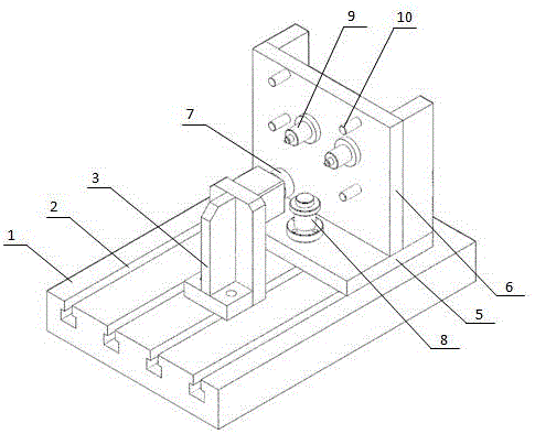
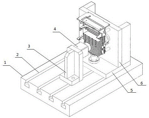
[0013] Such as figure 1 , figure 2 As shown, it includes a bottom plate 1, a positioning seat, and a pressing seat 3. The positioning seat includes a substrate 5 and a support plate 6 vertically arranged on the substrate. The lower part of the substrate 5 is provided with a sliding block (not (Shown in the figure), the slider and the sliding groove 2 are both T-shaped structures, the upper part of the base plate is provided with a support frame 8, and the side of the support plate facing the compression seat 3 is provided with a positioning pin 9 and a support pin 10; The seat 3 is fixed on the bottom plate, the upper end of the compression seat 3 is fixed with a cylinder 4, the piston rod of the cylinder 4 is facing the support plate, and the end of the piston rod is provided with a rubber pressing block 7.
[0014] Among them, the chute 2 is arranged along the length of the bottom plate 1, and its length is less than the length of the bottom plate, so that a seal is formed on one side of the chute, so that in the clamping state, the slider abuts against the end face of the chute seal to achieve positioning The seat is fixed as a whole.
[0015] Such as Figure 1~Figure 3 As shown, when clamping, the front end face 21 of the radiator abuts on the support frame 8, the mounting plate 25 on the rear side 22 of the radiator is attached to the upper end face of the support plate 6, and the lower end face 24 of the radiator passes through the positioning pin 9 is positioned and supported by the support pin 10, and the heat sink 23 on the upper side of the radiator is pressed and fixed by the cylinder, which is simple and convenient to use and has high clamping efficiency.

PUM

no PUM

Description & Claims & Application Information

We can also present the details of the Description, Claims and Application information to help users get a comprehensive understanding of the technical details of the patent, such as background art, summary of invention, brief description of drawings, description of embodiments, and other original content. On the other hand, users can also determine the specific scope of protection of the technology through the list of claims; as well as understand the changes in the life cycle of the technology with the presentation of the patent timeline. Login to view more.

Similar technology patents

State-based system for automated shading

InactiveUS7941245B1Easy to useMinimize inconvenienceSampled-variable control systemsBurglar alarm by openingState of the EnvironmentState specific
Owner:POPAT PRADEEP PRANJIVAN

Classification and recommendation of technical efficacy words

  • Easy to use
  • Improve clamping efficiency

Laser assisted total joint arthroplasty

InactiveUS20090234360A1Easy to useNon-surgical orthopedic devicesSurgical sawsLaser assistedLaser guidance
Owner:ALEXANDER VLADIMIR

System, method, and apparatus for settlement for participation in an electric power grid

ActiveUS8583520B1Communication securityEasy to useLevel controlCoin-freed apparatusNetwork managementGrid operator
Owner:CAUSAM ENERGY INC

People also interested in

Why Eureka
Try Eureka