Rotation device and tower crane

A technology of tower cranes and slewing devices, which is applied in the engineering field and can solve problems such as the inability to reliably ensure the safety of jacking and heightening

Inactive Publication Date: 2016-12-07
ZOOMLION HEAVY IND CO LTD
View PDF6 Cites 2 Cited by
  • Summary
  • Abstract
  • Description
  • Claims
  • Application Information

AI Technical Summary

Problems solved by technology

Especially when the tower crane is jacking and heightening, it is easy to cause the upper tower (tower head) to rotate relative to the lower tower (to

Method used


Image

  • Rotation device and tower crane
  • Rotation device and tower crane
  • Rotation device and tower crane

Examples


Embodiment Construction

[0039] Specific embodiments of the present invention will be described in detail below in conjunction with the accompanying drawings. It should be understood that the specific embodiments described here are only used to illustrate and explain the present invention, and are not intended to limit the present invention.

[0040] In the present invention, the orientation words used such as "up, down, left and right" usually refer to the up, down, left and right shown in the accompanying drawings; "inside and outside" refer to the outline relative to each part itself inside and outside.

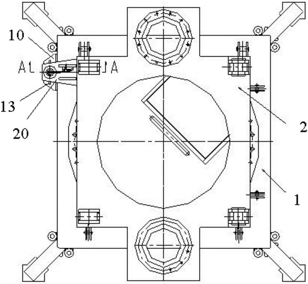
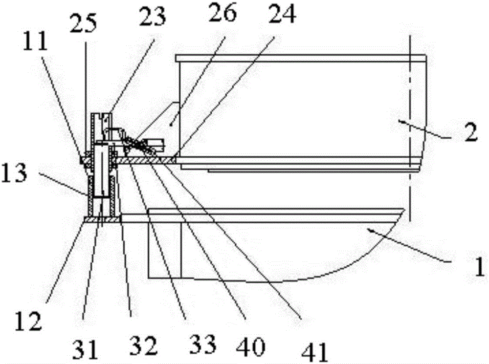
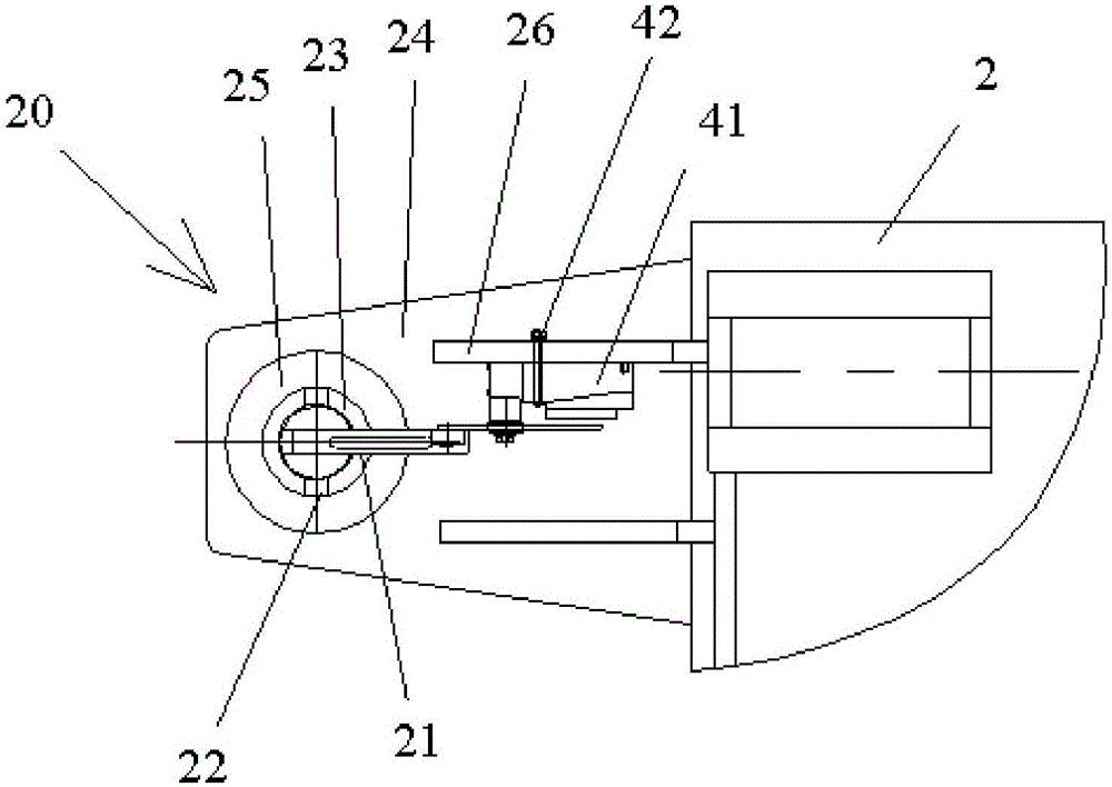
[0041] The invention provides a rotary device, such as figure 1 As shown, the slewing device includes a first support 1 and a second support 2 that can rotate relatively. The first support 1 is provided with a locking member 10, and the second support 2 is provided with a first stopper. 21 of the positioning piece 20, the rotary device also includes a limit piece 30 and a detection piece 40 for ...


PUM


Abstract

The invention relates to the field of engineering and discloses a rotation device and a tower crane. The rotation device comprises a first support (1) and a second support (2) which can rotate relatively. The first support is provided with a clamping part (10). The second support is provided with a positioning part (20) provided with a first limiting part (21). The rotation device further comprises a limiting part (30) and a detection part (40) used for detecting the position state of the limiting part. The limiting part (30) is installed between the clamping part (10) and the positioning part (20) and is used for limiting the rotation between the first support and the second support when matched with the first limiting part (21). The detection part (40) is electrically connected with a rotation control mechanism so as to control a rotation drive mechanism to be in a locked state when the limiting part (30) is matched with the first limiting part (21). It is effectively ensured that an upper vehicle cannot rotate relative to a lower vehicle when the crane is heightened and lifted, and construction safety is reliably ensured.

Description

technical field [0001] The invention relates to the field of engineering, in particular to a slewing device and a tower crane. Background technique [0002] As a kind of engineering machinery used to lift and carry heavy objects, crane safety is one of the most important metrics. Among them, whether it is a fixed crane represented by a tower crane or a mobile crane represented by a truck crane, most of them have a lifting mechanism, a luffing mechanism, and a slewing mechanism. [0003] The slewing structure is arranged between the upper car (upper tower) and the lower car (lower tower), in order to realize the relative rotation of the upper car (upper tower) and the lower car (lower tower). Especially when the tower crane is jacking and heightening, it is easy to cause the upper tower (tower head) to rotate relative to the lower tower (tower body) under the action of external forces such as wind, and it is impossible to reliably ensure the height of the jacking and heighte...

Claims


Application Information

Patent Timeline
IPC IPC(8): B66C23/84
CPCB66C23/84
Inventor 谢江平刘毅
Owner ZOOMLION HEAVY IND CO LTD
Why Eureka
Try Eureka