Cleaning machine for textile machine

A technology for textile machinery and cleaning machines, applied in the field of cleaning machines, can solve the problems of unintentional collision of rubber blowing nozzles, loss of cleaning function of cleaning machines, blockage of filter screens, etc., so as to improve air conditions in workshops, and be beneficial to spinning production and cleaning. good effect

Inactive Publication Date: 2016-12-07
HAIAN TEXTILE MACHINERY
View PDF0 Cites 1 Cited by
  • Summary
  • Abstract
  • Description
  • Claims
  • Application Information

AI Technical Summary

Problems solved by technology

[0003] 1. As for the blower outlet of the cleaning machine of the doubling frame, spinning frame, and winding machine, a blowing pipe is generally connected from the main machine (generally, this pipe is relatively far away from the main machine), and the part that needs to be cleaned in the textile machine , setting various lengthened rubber nozzles can also clean the main cleaning parts of the textile machine very well, but the problem with this setting is that the rubber nozzles are prone to artificial collisions during use, and there are still long Over time, the natural deformation of the rubber after aging can easily lead to the cleaning of the parts that need to be cleaned, causing the cleaning machine to lose its cleaning function and become a decoration
[0004] 2. The general textile machinery cleaning machine is equipped with a suction box on the suction pipe, and a filter is installed in the suction box. After the cleaning machine works for one to two hours, the filter will be blocked. If the filter is not replaced in time net, the cleaning machine cannot achieve the effect of absorbing cotton, and the cleaning machine moves back and forth ineffectively on the textile machine, which is like an empty device

Method used


Image

  • Cleaning machine for textile machine
  • Cleaning machine for textile machine
  • Cleaning machine for textile machine

Examples


Embodiment

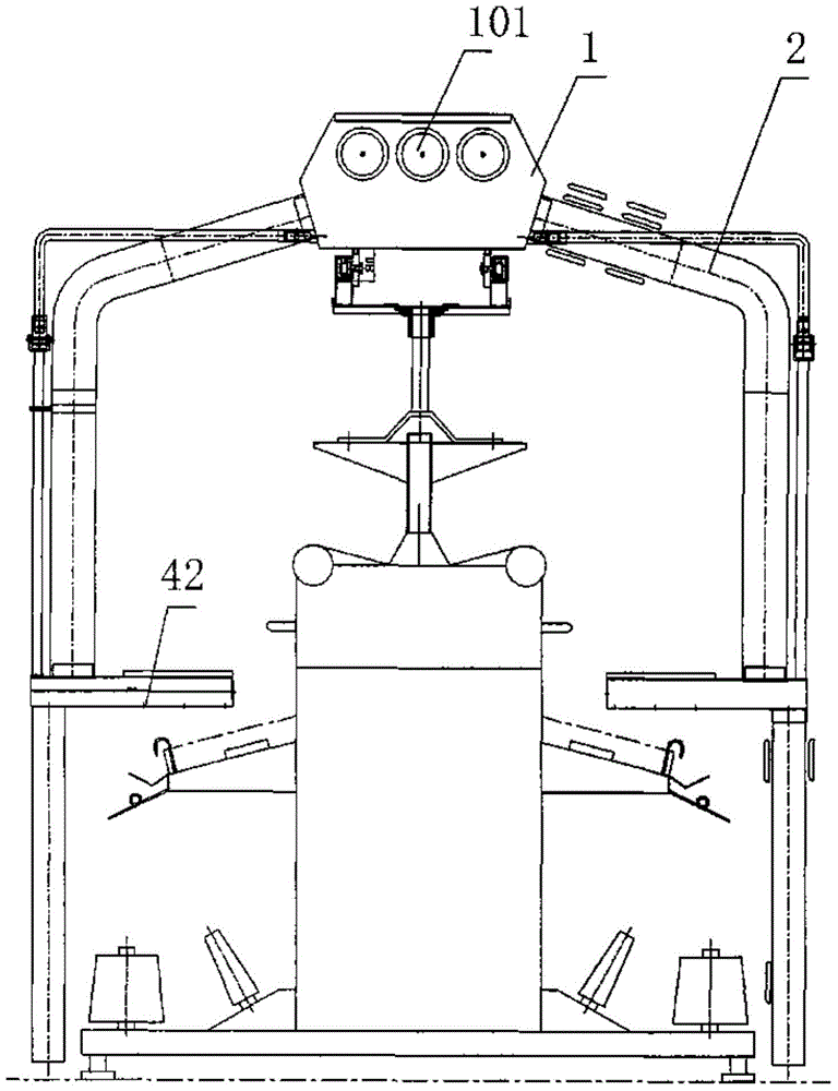
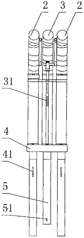
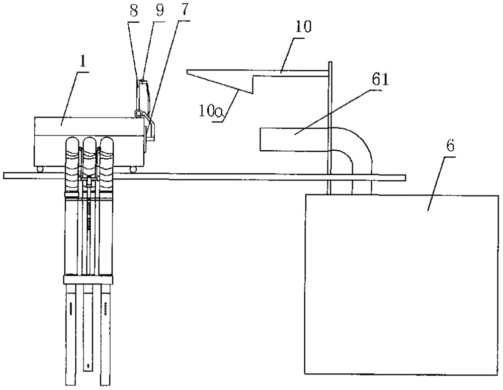
[0023] Example: see Figures 1 to 6 As shown, a textile machinery cleaning machine includes a cleaning main machine 1, a blowing pipe 2 and a suction pipe 3 are arranged on the cleaning main machine 1, a blowing box 4 is fixed on the blowing pipe 2, and a blowing box 4 is formed on the blowing box 4 to directly face The blowing hole 41 of the textile machinery needs to be cleaned, and the blowing hole 41 is connected with the blowing pipe 2. The blowing box 4 is formed with a suction hole 42 matched with the blowing hole 41, and the suction hole 42 is connected with the suction pipe 3.

[0024] The ground suction pipe 5 is fixed on the blowing box 4 and communicated with the suction pipe 3, and the ground suction pipe 5 is provided with a cotton suction port 51 in the air of the ground suction pipe.

[0025] The air suction pipe 3 is provided with a cotton suction opening 31 in the air.

[0026] The air suction hole 42 is arranged to face the working surface of the textile ma...


PUM


Abstract

A cleaning machine for a textile machine comprises a main cleaning unit, wherein air blowing pipes and an air suction pipe are arranged on the main cleaning unit, an air blowing box is fixed on the air blowing pipes, air blowing holes directly facing a cleaning requiring part of the textile machine are formed in the air blowing box and are in commination connection with the air blowing pipes, and air suction holes matched with the air blowing holes are formed in the air blowing box and are in commination connection with the air suction pipe. The air blowing holes of the cleaning machine are closest to the cleaning requiring part, so that the best cleaning effect is realized, and the condition that the cleaning requiring part is not cleaned can be avoided even under conditions of accidental collision and the like; the cleaning effect is guaranteed by means of the plurality of air suction holes for air suction; sucked cotton waste is cleaned timely, manual cleaning is not needed, and a filter screen is not blocked.

Description

Technical field: [0001] The invention relates to the technical field of cleaning machines, in particular to a cleaning machine used in conjunction with textile machinery. Background technique: [0002] Its weak point of the cleaning machine that the supporting use of existing textile machinery is: [0003] 1. As for the blower outlet of the cleaning machine of the doubling frame, spinning frame, and winding machine, a blowing pipe is generally connected from the main machine (generally, this pipe is relatively far away from the main machine), and the part that needs to be cleaned in the textile machine , setting various lengthened rubber nozzles can also clean the main cleaning parts of the textile machine very well, but the problem with this setting is that the rubber nozzles are prone to artificial collisions during use, and there are still long Over time, the natural deformation of the rubber after aging can easily lead to the cleaning of the parts that need to be cleane...

Claims


Application Information

Patent Timeline
Patent Type & Authority Applications(China)
IPC IPC(8): D01H11/00
Inventor 王明晶
Owner HAIAN TEXTILE MACHINERY
Why Eureka
Try Eureka