
Wheel-rail transfer mud system

A mud and transfer technology, applied in wellbore/well components, earthwork drilling, flushing wellbore, etc., can solve the problems of difficult layout of pipelines between tanks, incomplete discharge of mud, and inability to achieve centralized discharge of cuttings, etc. The effect of improving the safety factor

Active Publication Date: 2018-12-04
BAOJI PETROLEUM MASCH CO LTD +2
View PDF6 Cites 0 Cited by
  • Summary
  • Abstract
  • Description
  • Claims
  • Application Information

AI Technical Summary

Problems solved by technology

[0003] The purpose of the present invention is to provide a wheel-rail transfer type mud system, which solves the problems of incomplete mud discharge, difficult arrangement of pipelines between tanks and centralized discharge of cuttings in the prior art

Method used


Image

  • Wheel-rail transfer mud system
  • Wheel-rail transfer mud system
  • Wheel-rail transfer mud system

Examples


Embodiment Construction

[0025] The present invention will be described in detail below in conjunction with the accompanying drawings and specific embodiments.

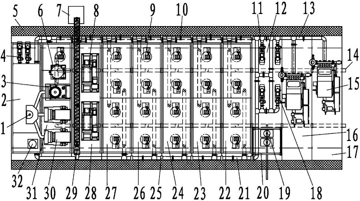
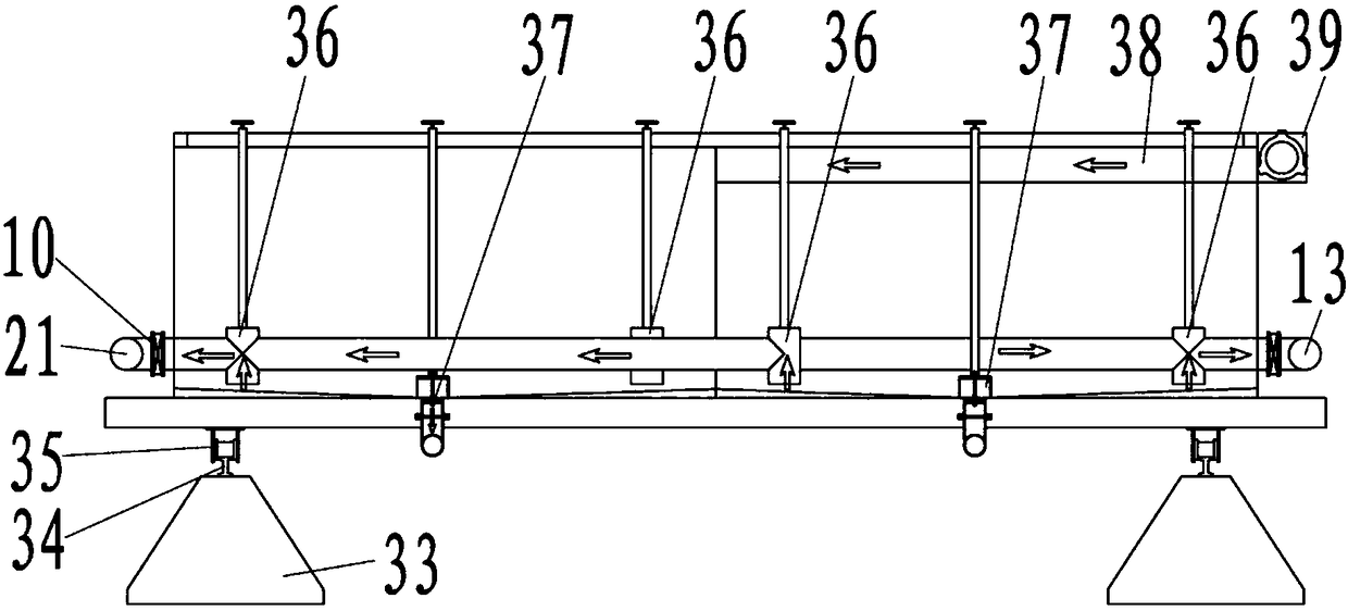
[0026] refer to figure 1 , figure 2 , Figure 5 , the structure of the present invention is, comprise the water tank 2 that closes discharge with zero clearance, vibrating screen tank 31, purification skid 28, intermediate tank 27, 1# reserve tank 26, 2# reserve tank 24, 3# reserve tank 23, suction Tank 22, mixing skid 12, mud pump skid Ⅰ 16, mud pump skid Ⅱ 17, above-mentioned water tank 2, vibrating screen tank 31, purification skid 28, intermediate tank 27, 1# reserve tank 26, 2# reserve tank 24, 3# The storage tank 23, the suction tank 22, the mixing skid 12, the mud pump skid I 16, and the mud pump skid II 17 are respectively equipped with respective roller assemblies 35 on the lower end surfaces, and all the roller assemblies 35 are placed on the guide rail 34 in turn, and the guide rail 34 is installed On the guide rail support 33,...


PUM


Abstract

The invention discloses a wheel-track transporting-type slurry system. The wheel-track transporting-type slurry system comprises a water tank, a vibrating screen tank, a purifying pry, a middle tank, a plurality of storing tanks, a suction tank, a mixing pry, a first slurry pump pry and a second slurry pump pry. A liquid-gas separator, a slurry distributing device and water pumps are arranged on the a bottom pry of the water tank; vibrating screens, a cleaning device and a gas removing device are arranged on a bottom pry of the vibrating screen tank; two centrifugal machines are installed in the inside space of the purifying pry, a screw conveyer and the cleaning device and liquid supplying pumps of the centrifugal machines are installed at the lower portions of the purifying pry, a rock debris collecting box is connected to an opening in the upper portion of the screw conveyer, two filling pumps, two mixing pumps, mixing hoppers and a large-bag-material lifting mechanism are arranged on the mixing pumps; the first slurry pump pry and the second slurry pump pry are provided with slurry pumps respectively, and the two slurry pumps are externally and jointly communicated with a slurry suction pipe. By means of the wheel-track transporting-type slurry system, the manufacturing cost is reduced, and the installing time is shortened.

Description

technical field [0001] The invention belongs to the technical field of oil drilling equipment, and relates to a wheel-rail transfer type mud system. Background technique [0002] In recent years, with the continuous development of wheel-rail transfer drilling rigs, the mud system for wheel transfer must be updated. However, the current structural design has problems with incomplete mud discharge, inability to arrange pipelines between tanks, and centralized discharge of cuttings. Insufficient etc. obviously impede the overall operating efficiency of the drilling rig. Contents of the invention [0003] The purpose of the present invention is to provide a wheel-rail transfer type mud system, which solves the problems of incomplete mud discharge, difficult arrangement of pipelines between tanks and centralized discharge of cuttings in the prior art. [0004] The technical solution adopted in the present invention is a wheel-rail transfer type mud system, including a close-di...

Claims


Application Information

Patent Timeline
Patent Type & Authority Patents(China)
IPC IPC(8): E21B21/00
CPCE21B21/00
Inventor 张虎山赵鹏杜永军覃建刘静
Owner BAOJI PETROLEUM MASCH CO LTD
Learn More