
Electric heating constant-temperature air blowing drying box

A technology of blast drying box and drying box, which is applied in the direction of drying solid materials, dry goods handling, drying room/container, etc. It can solve the problems of difficult control of inner tank temperature, inconvenient taking of experimental objects, and slow heating of inner tank, etc. Achieve the effect of simple structure, wide application range and uniform internal temperature

Inactive Publication Date: 2016-12-07
镇江奥美机电设备有限公司
View PDF0 Cites 0 Cited by
  • Summary
  • Abstract
  • Description
  • Claims
  • Application Information

AI Technical Summary

Problems solved by technology

[0002] The electric constant temperature blast drying oven is one of the most widely used laboratory equipment in various laboratories. It is the main tool used for precision constant temperature and auxiliary heating in colleges, universities, industrial and mining enterprises, and scientific research units; the traditional drying oven is generally They are all controlled manually, and the control dial is at the bottom of the drying box. It is very inconvenient to squat down when operating. In addition, the internal heating device is installed at the bottom of the inner tank, and the heating is uneven, which causes the side wall of the inner tank to be heated. Slower, the temperature at the bottom is higher and the temperature at the upper part is lower. Similarly, the heat dissipation is uneven, the internal temperature of the inner tank is not easy to control, and it is inconvenient to take the test object, which will bring losses to the user.

Method used


Image

  • Electric heating constant-temperature air blowing drying box
  • Electric heating constant-temperature air blowing drying box
  • Electric heating constant-temperature air blowing drying box

Examples


Embodiment Construction

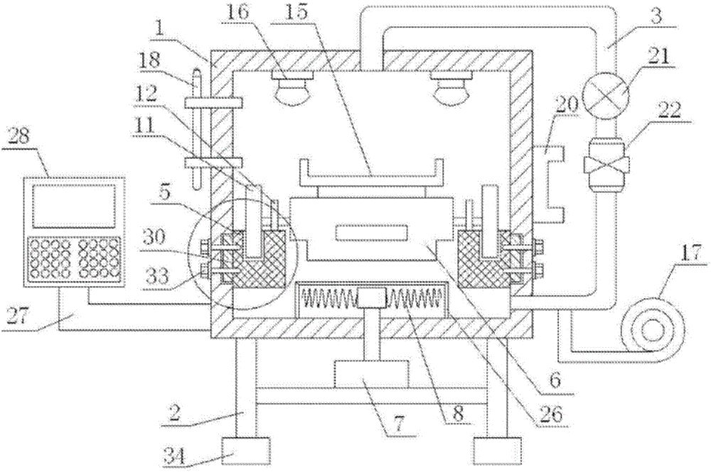
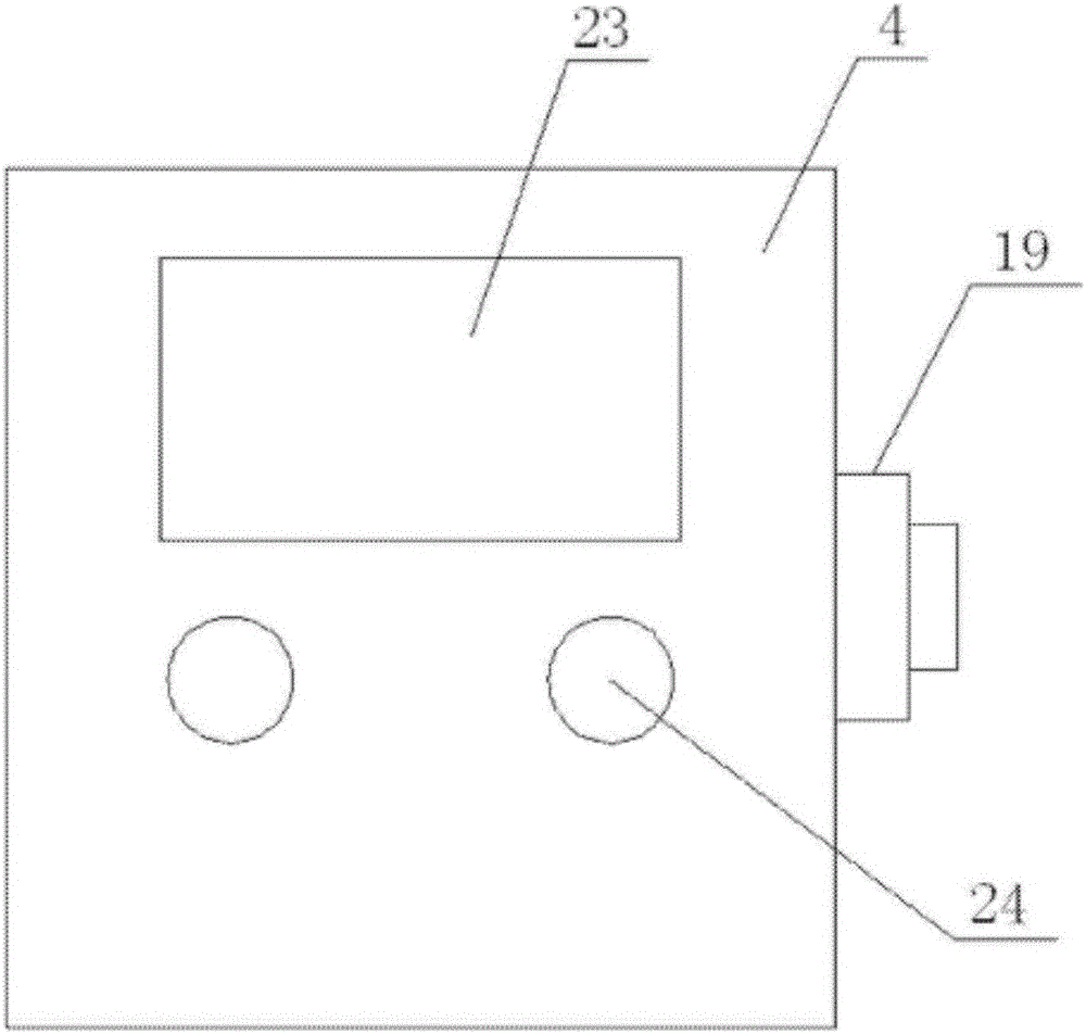
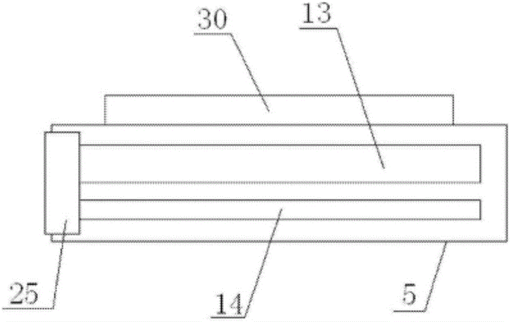
[0017] refer to Figure 1 to Figure 5 A kind of electric heating constant temperature blast drying box shown, comprises drying box body 1 and frame 2, and the circulation pipe 3 that is arranged on drying box body 1, and the box door 4 that is arranged on drying box body 1, and symmetrical Two fixing parts 5 arranged on the inner wall of the drying box body 1, and a support plate 6 arranged in the drying box body 1, the drying box body 1 is arranged on the frame 2, and the frame 2 is provided with a heating The heater 7, the output end of the heater 7 extends to the inner bottom of the drying box body 1, and the output end of the heater 7 extending to the inner bottom of the drying box body 1 is provided with a heating wire ring 8, and the support plate 6 has two Two first rotating shafts 9 and two second rotating shafts 10 are provided in lateral symmetry, large rollers 11 are provided on the two first rotating shafts 9, small rollers 12 are provided on the two second rotatin...


PUM


Abstract

The invention discloses an electric heating constant-temperature air blowing drying box. The electric heating constant-temperature air blowing drying box comprises a drying box body, a machine frame, a circulation pipe arranged on the drying box body, a box door arranged on the drying box body, two fixing portions symmetrically arranged on the inner wall of the drying box body, and a supporting plate arranged inside the drying box body, wherein the drying box body is arranged on the machine frame; a heater is arranged on the machine frame, and the output end of the heater extends to the bottom inside the drying box body and is provided with a heating iron wire ring; two first rotary shafts and two second rotary shafts are symmetrically arranged on two sides of the supporting plate; the two first rotary shafts are both provided with large roller wheels; the two second rotary shafts are both provided with small roller wheels; the fixing portions are provided with first roller grooves matched with the large roller wheels and further provided with second roller grooves matched with the small roller wheels; the upper portion of the supporting plate is provided with a fixing seat; and the circulation pipe is connected with an air blower. The electric heating constant-temperature air blowing drying box saves energy, is uniform in internal temperature, and is controllable in temperature.

Description

technical field [0001] The invention relates to an electric heating constant temperature blast drying oven. Background technique [0002] The electric constant temperature blast drying oven is one of the most widely used laboratory equipment in various laboratories. It is the main tool used for precision constant temperature and auxiliary heating in colleges, universities, industrial and mining enterprises, and scientific research units; the traditional drying oven is generally They are all controlled manually, and the control dial is at the bottom of the drying box. It is very inconvenient to squat down when operating. In addition, the internal heating device is installed at the bottom of the inner tank, and the heating is uneven, which causes the side wall of the inner tank to be heated. Slower, the temperature at the bottom is higher and the temperature at the upper part is lower. Similarly, the heat dissipation is uneven, the internal temperature of the inner tank is not...

Claims


Application Information

Patent Timeline
Patent Type & Authority Applications(China)
IPC IPC(8): F26B9/06F26B21/00F26B21/04F26B25/00F26B25/08F21V33/00F21Y115/10F21W131/403
CPCF26B9/06F21V33/00F21W2131/403F26B21/004F26B21/04F26B25/003F26B25/08
Inventor 朱彬张志杰朱茂文
Owner 镇江奥美机电设备有限公司
Learn More