An anti-heating device for a diversion plate and a power transmission line with the device

A technology for heating devices and transmission lines, which is applied to the spatial arrangement/configuration of cables, etc., which can solve the problems of increasing jumper connection point heating, increased contact resistance, and large contact resistance, so as to achieve accurate and reliable early warning indications and eliminate contact resistance. The effect of increasing and eliminating the hidden danger of fever

Active Publication Date: 2017-10-13
广州开能电气技术有限公司
View PDF8 Cites 1 Cited by
  • Summary
  • Abstract
  • Description
  • Claims
  • Application Information

AI Technical Summary

Problems solved by technology

[0002] In the power transmission line, the crimping type strain clamp is usually used to connect the main conductor and the jumper. In the structure of connecting the jumper through the drainage terminal board, since the material of the jumper clamp is usually aluminum with low hardness (generally Use pure aluminum), after the compression tube of the drainage terminal board is crimped with the wire, it is easy to cause thermal expansion and contraction of the crimping point due to the influence of the environment and operating temperature, resulting in an increase in contact resistance. The jumper clamp has the same problem; in addition, because the connection between the strain-resistant clamp drain terminal board and the jumper clamp adopts a bolt crimping structure, and the terminal board is made of pure aluminum material with low hardness, the jumper wire and the main wire The vibration generated by the swing directly leads to the loosening of the crimping point, resulting in a contact resistance greater than the design requirement; this connection structure often causes overheating of the jumper connection point and the tension clamp, which threatens the safe operation of the transmission line. During operation, when the heat of the tension clamp exceeds the design requirements, technicians cannot accurately and timely find the fault point, which affects the efficiency of line maintenance
[0003] figure 1 It is a schematic diagram of the conventional jumper structure of the transmission line in the prior art, and the crimping type strain clamp is connected between the main wire and the jumper, figure 2 It can be seen that there are 3 hot spots at one jumper, that is, there are a total of 6 hot spots at both ends of the jumper symmetrically in the transmission line, and the jumper is added. The probability of heating at the connection point. During long-term use, the drainage terminal board and the crimping point will overheat, which will affect the safe operation of the transmission line.

Method used


Image

  • An anti-heating device for a diversion plate and a power transmission line with the device
  • An anti-heating device for a diversion plate and a power transmission line with the device
  • An anti-heating device for a diversion plate and a power transmission line with the device

Examples


Embodiment Construction

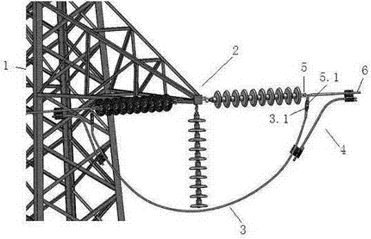
[0031] like image 3 As shown, the power transmission line with detachable diversion plate anti-heating device of the present invention includes pole tower 1, "T" shaped insulator string 2, jumper wire 3, diversion plate anti-heating device 4, strain clamp 5 and main conductor 6. Jumper wire 3 straddles the horizontal sides of the "T" shaped insulator string to image 3 Take the jumper connection structure on the right side of the horizontal as an example, the drain terminal board 5.1 at one end of the strain clamp 5 and the jumper clamp 3.1 of the jumper 3 are crimped and fixed, such as by bolt crimping; the other end of the strain clamp It is crimped and fixed with the main wire 6; the anti-heating device 4 of the drain plate is arranged on one side of the strain clamp 5, and the two ends are respectively connected and fixed with the jumper wire 3 and the main wire 6.

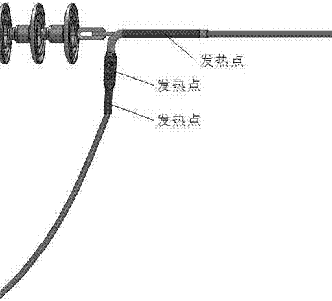
[0032] like Figure 4 As shown, the anti-heating device 4 of the drainage plate is composed of a bypass ...


PUM


Abstract

The invention relates to the technical field of power transmission lines, and discloses a drainage plate heating prevention device and the power transmission line with the same. The power transmission line comprises a tower, a jumper wire, a drainage plate heating prevention device body, a strain clamp and a main guide wire; and the drainage plate heating prevention device is characterized in that the drainage plate heating prevention device body is arranged at one side of the strain clamp and is connected and fixed to the jumper wire and the main guide wire. The jumper wire is connected through the drainage plate heating prevention device body, so that most current which flows through the jumper wire, the strain clamp and a drainage terminal board can be shunted; and heating of the strain clamp is reduced. An over-temperature warning monitor component is also arranged in the drainage plate heating prevention device, and a hidden trouble point is overhauled in a targeted manner, so that the running safety and reliability of the power transmission line are further improved.

Description

technical field [0001] The invention relates to the technical field of power transmission lines, in particular to a device for preventing overheating of a power transmission line diversion plate. Background technique [0002] In the power transmission line, the crimping type strain clamp is usually used to connect the main conductor and the jumper. In the structure of connecting the jumper through the drainage terminal board, since the material of the jumper clamp is usually aluminum with low hardness (generally Use pure aluminum), after the compression tube of the drainage terminal board is crimped with the wire, it is easy to cause thermal expansion and contraction of the crimping point due to the influence of the environment and operating temperature, resulting in an increase in contact resistance. The jumper clamp has the same problem; in addition, because the connection between the strain-resistant clamp drain terminal board and the jumper clamp adopts a bolt crimping s...

Claims


Application Information

Patent Timeline
Patent Type & Authority Patents(China)
IPC IPC(8): H02G7/20
CPCH02G7/20
Inventor 徐卫东
Owner 广州开能电气技术有限公司
Why Eureka
Try Eureka