Device for producing S-shaped joint of rectangular busbar

A technology for manufacturing devices and rectangular busbars, which is applied in the field of manufacturing devices for rectangular busbar S-shaped joints, to achieve the effects of eliminating hidden dangers of heating, ensuring safe operation, and reducing labor intensity

Active Publication Date: 2011-05-04
STATE GRID CORP OF CHINA +2
View PDF5 Cites 3 Cited by
  • Summary
  • Abstract
  • Description
  • Claims
  • Application Information

AI Technical Summary

Problems solved by technology

In the prior art, for the installation method of the S-bend joint of the 10kV side outlet rectangular busbar bridge of the main transformer, one is to use machine tool punching, which is not suitable for on-site construction work because of the heavy equipment; Although it can be suitable for on-site construction, this manufacturing method has the following defects: due to uneven joint length and inconsistent curvature, it is easy to cause busbar metal fatigue and increase contact resistance, which affects the service life of the busbar bridge; after the equipment is put into operation, especially The busbar often has a large current flow, which can easily cause the joint to heat up, causing the heat shrink box of the joint to often melt and fall off; and its labor intensity is high, requiring the cooperation of many people, wasting financial and material resources, poor installation quality, and affecting work efficiency

Method used


Image

  • Device for producing S-shaped joint of rectangular busbar
  • Device for producing S-shaped joint of rectangular busbar
  • Device for producing S-shaped joint of rectangular busbar

Examples


Embodiment Construction

[0019] The present invention will be further described below in conjunction with the accompanying drawings and embodiments.

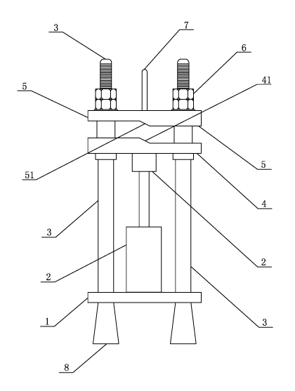
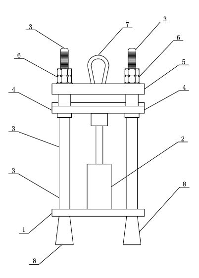
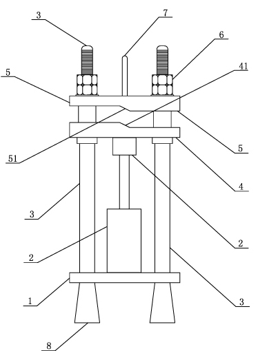
[0020] Such as figure 1 , 2 As shown, a rectangular busbar S-shaped joint manufacturing device includes a base plate 1 and a hydraulic jack 2. The base plate 1 is rectangular, and four columns 3 are vertically arranged at the four corners of the rectangular base plate 1. The hydraulic jack 2 is installed The middle part of the rectangular bottom plate 1; above the hydraulic jack 1 and the upper part of the column 3, a movable "S"-shaped lower steel plate 4 is sleeved;

[0021] Above the "S"-shaped lower steel plate 4, an "S"-shaped upper steel plate 5 is sleeved. It is fixed on the column 3; the "S"-shaped lower steel plate 4 can move vertically along the column 3 between the "S"-shaped upper steel plate 5 and the head of the hydraulic jack 2.

[0022] The shape of the "S" type upper steel plate 5 is: the left part of the lower surface is thick, the...


PUM


Abstract

The invention discloses a device for producing an S-shaped joint of a rectangular busbar, which comprises a baseplate and a hydraulic jack, wherein the baseplate is rectangular, four stand columns are respectively arranged at four corners of the rectangular baseplate, and the hydraulic jack is arranged in the middle part of the rectangular baseplate; a movable S-shaped lower steel plate is sleeved above the hydraulic jack and on the upper parts of the stand columns; an S-shaped upper steel plate is sleeved above the S-shaped lower steel plate, the shape of the S-shaped upper steel plate is fitted with that of the S-shaped lower steel plate, and the S-shaped upper steel plate is fixed on the stand columns by nuts; and the S-shaped lower steel plate can make a vertical movement between the S-shaped upper steel plate and the S-shaped lower steel plate along the stand columns. The device disclosed by the invention has the advantages that the device is light, simple in operation, flexible, safe and reliable; the produced S-shaped joint is uniform in curved part, even in lapped seam, and tidy and beautiful after installation; the labor intensity of the operating personnel is reduced, the installation process and the working efficiency are improved, and the propose of eliminating the hidden trouble of heating of the busbar joint can be achieved, thereby ensuring the safe operation of the busbar device which is put into operation.

Description

technical field [0001] The invention belongs to the technical field of crimping devices for rectangular busbar S-bend joints of 10kV bus bridges, and in particular relates to a manufacturing device for rectangular busbar S-shaped joints. Background technique [0002] At present, because the 10kV bus bridge is straight on the horizontal plane, the length is generally 10 meters to 20 meters, and the length of the copper bar is generally about 6 meters, so most bus bridges have joints. In order to ensure the straightness of the busbar bridge on the horizontal plane, an "S" bend joint must be made at the joint for lap joint. In the prior art, for the installation method of the S-bend joint of the 10kV side outlet rectangular busbar bridge of the main transformer, one is to use machine tool punching, which is not suitable for on-site construction work because of the heavy equipment; Although it can be suitable for on-site construction, this manufacturing method has the followin...

Claims


Application Information

Patent Timeline
Patent Type & Authority Applications(China)
IPC IPC(8): B21D5/00
Inventor 黄维谋
Owner STATE GRID CORP OF CHINA
Why Eureka
Try Eureka