Power distribution unit and movable type elastic busbar for the same

A power distribution device, mobile technology, applied in the direction of coupling devices, circuits, electrical components, etc., can solve the problems of adding terminal blocks, circuit virtual connections, inconvenient system adjustments in the later stage, etc., to ensure contact pressure, ensure stability, Ease of replacement and system maintenance

Pending Publication Date: 2018-03-09
SOOAR TIANJIN ELECTRICAL EQUIP CO LTD
View PDF1 Cites 1 Cited by
  • Summary
  • Abstract
  • Description
  • Claims
  • Application Information

AI Technical Summary

Problems solved by technology

Because the outlet end of the main switch needs to be connected with multiple electric wires, the multiple electric wires connected to the main switch end need to be crimped together with a terminal, and then connected to the outlet end of the main switch, so it has the following disadvantages: (1 ) The installation process is too complicated, the installation efficiency is low, the more wires, the more messy the wiring; (2) The more sub-switches, the more electrical wires connected to the outlet end of the main switch, making it more difficult for multiple electrical wires to be connected to the outlet end of the main switch Large; (3) there is waste in the use of electric wires, and the cost is high
[0004] The existing conductive assembly in the form of a combination of electric wires and busbars is composed of two electric wires and a bipolar busbar. One end of the electric wire is connected to the outlet end of the main switch, and the other end of the electric wire is connected to the busbar through a terminal block. Then the bus bar is connected to the incoming line end of the sub-switch, and the electric energy enters the sub-switch from the main switch through the electric wire and the bus bar. The connection method is welding connection or screw connection, which has the following disadvantages: (1) The installation process is complicated , the installation efficiency is low; (2) the wiring head is added, the parts are many, and the cost is high; (3) the position between the sub-conductors in the bus bar is fixed, and it cannot be adapted to the switch of various wiring ports, nor can it be used according to the system make adjustments
[0005] Existing conductive components in the form of bus bars, the bus bar has multiple poles, each pole includes multiple conductors, and the electric energy flows from the main switch through multiple conductors into the sub-switches, or the electric energy flows from the sub-switches into the main switch through multiple conductors, The connection methods between the conductors of this type of busbar include screw connection, welding connection or crimping connection, but it has the following disadvantages: (1) Busbars with welding or crimping connection methods: the sub-conductors need to be welded or crimped. On the main conductor, there are many processes, cumbersome packaging and transportation, long production cycle, and high positioning accuracy is required when welding or crimping, which increases the difficulty of production, and the position between the sub-conductors of the formed bus bar is fixed remain unchanged, cannot adapt to the switching requirements of various wiring ports, and cannot be adjusted according to the system; (2) Busbars connected by bolts or screws: screws and nuts are added, the number of parts is large, the cost is high, and the production process is many. The production cycle is long, and the loosening of screws or bolts will cause virtual connections in the circuit, posing safety hazards and easily causing major accidents, and the position between the sub-conductors of the formed bus bar is fixed, which cannot adapt to various wiring The switch requirements of the port cannot be adjusted according to the system.
[0007] (1) During the assembly process: the crimping frame 1 needs to line up and penetrate one end of the confluence body 3 sequentially, and the installation process is tedious; Between the set screws 2, precise positioning is required, and the installation is difficult; in order to ensure reliable contact between the joint piece 4 and the collector body 3, the set screws 2 need to be tightened, which has a long production cycle, heavy workload, and low efficiency; (2) In terms of structure: there is a hidden danger of screw loosening in a vibrating environment, which may easily cause unstable contact resistance; the crimping frame 1 is fixed with the set screw 2, and the process of tightening and loosening the set screw 2 requires a certain amount of room for movement, and The large volume of the wire crimping frame causes the overall volume of the busbar to be large, which is not conducive to the demand for miniaturization of the volume; there are many types of components, complex assembly, long production cycle, and high cost, which cannot meet the needs of fast delivery; (3) in the later stage In terms of system adjustment: because the crimping frame 1 is worn on the bus body 3, the number of crimping frames and connectors cannot be increased or decreased after the bus bar is installed, which is inconvenient for later system adjustments

Method used


Image

  • Power distribution unit and movable type elastic busbar for the same
  • Power distribution unit and movable type elastic busbar for the same
  • Power distribution unit and movable type elastic busbar for the same

Examples


Embodiment approach 1

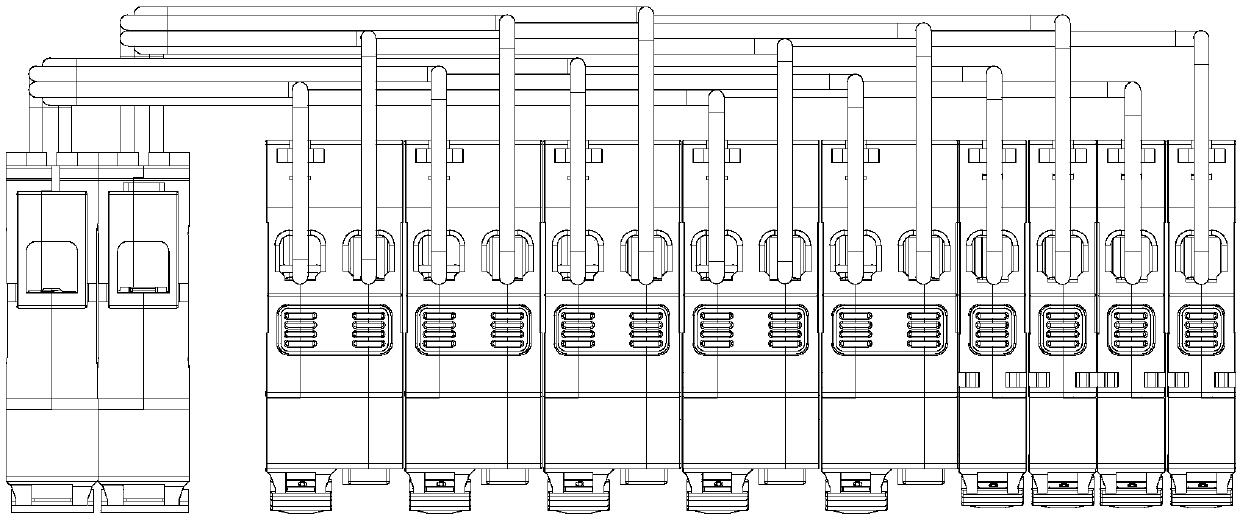
[0101] Such as Figure 4 to Figure 31 As shown, the present invention provides a mobile elastic busbar for power distribution devices, which includes: a main conductor 200, one end of which is connected to the main switch 500 of the power distribution device; at least two sub-conductors 300, the sub-conductors One end of the sub-conductor 300 is connected to the sub-switch 600 of the power distribution device, and the other end of the sub-conductor 300 can be fixed on the main conductor 200 with a predetermined clamping force. The junction of the conductor 300 and the general conductor 200 is collinear.

[0102] Specifically, the main conductor 200 is used to flow out from the main switch 500 or sink current into the main switch 500, and the sub-conductors 300 are used to flow in or flow out current to each sub-switch 600, and the length and shape of the sub-conductors 300 are Conductors of different shapes and lengths are made according to the number of poles of the sub-swit...

example

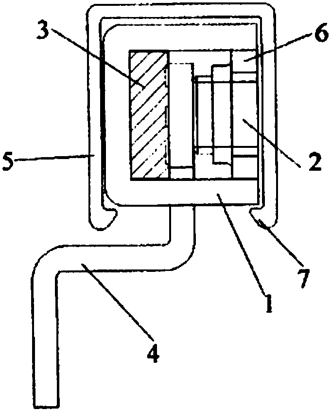
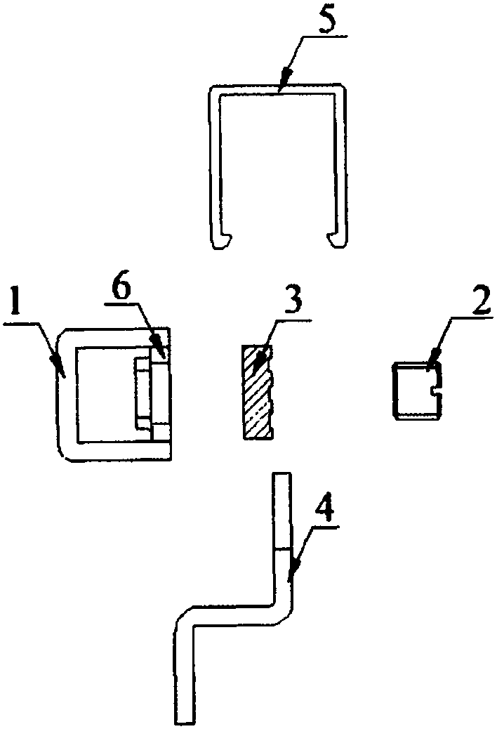
[0121] (1) When the sub-conductor 300 is made of non-elastic material, the conductive part is provided with a metal elastic part, and the elastic part is covered with an insulating cover 320, the material of each part and the coating on the main conductor 200 and the sub-conductor 300 can be as follows Setting (823 refers to DJB-823 solid film protective agent, 6μ refers to the thickness), wherein, the elastic part is blackened, and the insulating cover 320 is not treated:

[0122]

[0123]

[0124] For example, the rated current of each sub-switch 600 is 16A~25A, the conductivity of carbon spring steel or carbon steel after copper plating is greatly enhanced, and there are two points of contact, the contact resistance is very good, and it has anti-corrosion after coating 823. Wear resistance, the service life can reach 20 years. When the material is copper, its electrical conductivity is better, and it has anti-wear performance after tin or 823 is coated. When the materi...

Embodiment approach 2

[0135] Such as Figure 5 , Figure 8 and Figure 11 As shown, the present invention also provides a power distribution device, which includes a housing 100, a main switch 500, at least two sub-switches 600, and a mobile elastic busbar for power distribution devices as described above, the main switch 500 and at least two The two sub-switches 600 are fixed in the housing 100, specifically on the rear wall of the housing 100, and the movable elastic busbar is connected between the main switch 500 and the sub-switch 600. The structure, working principle and beneficial effect of the mobile elastic busbar for the power distribution device are the same as those of the first embodiment, and will not be repeated here, wherein, each sub-conductor 300 is vertically connected through an adjustable conductive part With respect to the main conductor 200 , the vertical includes being perpendicular to a plane parallel to the rear wall of the housing 100 or perpendicular to a plane perpendi...


PUM


Abstract

The invention provides a mobile elastic busbar for a power distribution device, which includes: a main conductor, one end of which is connected to the main switch of the power distribution device; at least two sub-conductors, one end of which is connected to the sub-switch of the power distribution device , the other end of the sub-conductor can be moved on the main conductor with a predetermined clamping force, and the joints between the sub-conductors and the main conductor of the same phase are collinear. The present invention also provides a power distribution device, which includes a housing, a main switch, at least two sub-switches and the above-mentioned movable elastic busbar for the power distribution device, the main switch and the sub-switches are fixed in the housing, and the movable elastic busbar Connected between the main switch and the branch switch. The present invention also provides a power distribution device, which includes a main switch, at least two sub-switches, and the above-mentioned movable elastic busbar for the power distribution device connected between the main switch and the sub-switches. The position of the sub-conductor of the invention can be adjusted according to the requirements of the wiring port, the contact is stable and reliable, and the installation and disassembly are simple and convenient.

Description

technical field [0001] The invention relates to the technical field of electrical appliances, and relates to a mobile elastic busbar for a power distribution device and a power distribution device. Background technique [0002] In the low-voltage power distribution system, the power distribution device includes a distribution box and a combiner box. The distribution box mainly plays the role of diversion, and the combiner box mainly plays the role of confluence. It mainly includes a casing, a main switch, multiple sub-switches and conductive components. The main switch and multiple sub-switches are placed in the casing. The main switch and multiple sub-switches are connected and transmit electric energy through conductive components, that is, the function of the conductive components is Carrying current, shunting or converging, the existing conductive components mainly have three forms: electric wire, bus bar, combination of electric wire and bus bar. [0003] Such as figu...

Claims


Application Information

Patent Timeline
Patent Type & Authority Applications(China)
IPC IPC(8): H01R4/48H01R25/16
CPCH01R4/48H01R25/16
Inventor 南添南寅姜永飞
Owner SOOAR TIANJIN ELECTRICAL EQUIP CO LTD
Why Eureka
Try Eureka