Wireless charging receiving coil and fabrication method thereof

A wireless charging and receiving coil technology, applied in the direction of transformer/inductor coil/winding/connection, circuit, inductor, etc., can solve the problems of large area and difficult integration, and achieve high quality factor and strong power receiving ability Effect

Active Publication Date: 2016-12-07
苏州创印电子科技有限公司
View PDF6 Cites 22 Cited by
  • Summary
  • Abstract
  • Description
  • Claims
  • Application Information

AI Technical Summary

Problems solved by technology

In the prior art, the wireless charging receiving coil is usually made of copper wires, and some researches are to print the wireless charging receiving coil on the PCB circuit board, but the wireless charging receiving coils are all rigid, And the area is large, it is difficult to integrate into portable and wearable devices

Method used


Image

  • Wireless charging receiving coil and fabrication method thereof
  • Wireless charging receiving coil and fabrication method thereof
  • Wireless charging receiving coil and fabrication method thereof

Examples


Embodiment 1

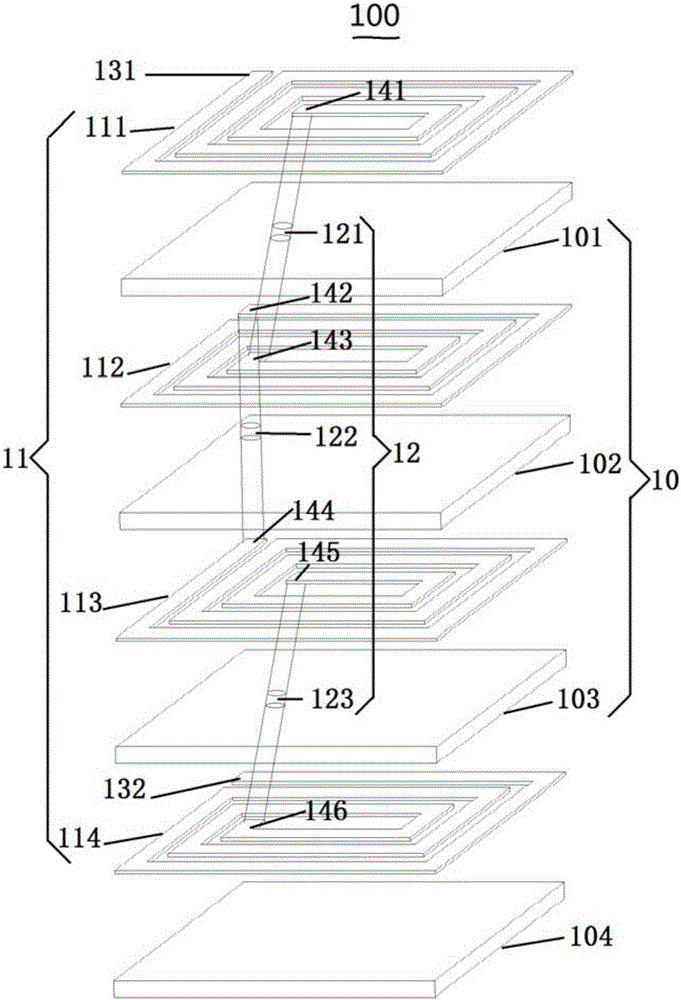
[0086] see figure 1 Shown is the structure of a wireless charging receiving coil provided in Embodiment 1 of the present application. The wireless charging receiving coil is a 4-layer series structure, including 1 layer of flexible substrate 104, 3 flexible insulating layers 10, and 4 conductive coil layers. 11, 3 vias 12, 2 terminals 131, 132. The bottom layer is the flexible substrate 104 as the base layer, the first conductive coil layer 114 , the first insulating layer 103 , the second conductive coil layer 113 , the second insulating layer 102 . . . up to the fourth conductive layer. The coil layers 111 are separated by an insulating layer 10 between adjacent conductive coil layers, forming a multi-layer structure in which the conductive coil layers and the insulating layers are alternately stacked.

[0087] The conductive coil layers of different layers have the same direction after being connected in series, and the inner end 146 of the first conductive coil layer 114 ...

Embodiment 2

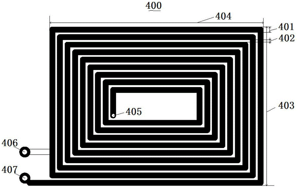
[0095] see Figure 4 Shown is the structure of a wireless charging receiving coil provided by Embodiment 2 of the present application. The wireless charging receiving coil is a 4-layer series-parallel structure, in which the upper two layers 211, 212 are connected in parallel, and the lower two layers 213, 214 are connected in parallel. , and then the upper two layers are connected in series with the lower two layers, which also includes 1 layer of flexible substrate 204 , 3 flexible insulating layers 20 , 4 conductive coil layers 21 , 5 via holes 22 , and 2 terminals 231 , 232 . The bottom layer is the base layer 204, and upwards are the first conductive coil layer 214, the first insulating layer 203, the second conductive coil layer 213, the second insulating layer 202... until the fourth conductive coil layer 211, Adjacent conductive coil layers are separated by insulating layers 20 to form a multi-layer structure in which conductive coils and insulating layers are stacked ...


PUM

PropertyMeasurementUnit
thicknessaaaaaaaaaa
thicknessaaaaaaaaaa
diameteraaaaaaaaaa

Abstract

The invention discloses a wireless charging receiving coil and a fabrication method thereof. The wireless charging receiving coil comprises a flexible substrate and a multi-layer flexible coil plate, wherein the multi-layer flexible coil plate comprises a plurality of conductive coil layers and a plurality of insulation layers which are alternatively laminated, a first conductive coil layer is arranged on one surface of the flexible substrate, a first insulation layer is arranged on the first conductive coil layer, meanwhile, a via hole is further formed in each insulation layer and is filled with a conductive material, the conductive material is used for connecting conductive coils in the plurality of conductive coil layers in series and/or in parallel to form a wireless charging coil, and the conductive coils in the plurality of conductive coil layers have the same current flowing direction. The wireless charging receiving coil provided by the invention has the advantages of ultra thinness, flexibility, ultra miniaturization and high quality factor and the like, is high in electric energy receiving capability, completely conforms to Qi standard and can be applied to a portable and wearable device.

Description

technical field [0001] The invention specifically relates to a wireless charging receiving coil and a preparation method thereof, belonging to the technical field of wireless charging. Background technique [0002] With the development of nanofabrication technology and very large integrated circuit (VLSI) technology, the size of electronic components and control chips is getting smaller and smaller, making electronic products develop in the direction of small, portable, integrated and wearable. At present, electronic products are required to be integrated and fully enclosed. It is necessary to improve the life and reliability of the products while being waterproof and dustproof. This poses challenges to the charging process of electronic products. For example, electronic products such as mobile phones and tablet computers (PDAs) contain A rechargeable battery (such as a lithium battery) is used to charge the internal battery of an electronic product. Generally, a charging in...

Claims


Application Information

Patent Timeline
Patent Type & Authority Applications(China)
IPC IPC(8): H02J50/10H01F38/14H01F27/28H01F27/32H02J7/00
CPCH01F27/2804H01F27/323H01F38/14H01F2027/2809H01F2038/143H02J7/025
Inventor 刘福星顾唯兵张克栋李亚邦崔铮
Owner 苏州创印电子科技有限公司
Why Eureka
Try Eureka