
Multi-sub-array antenna beam switching method based on maximization of power of receiving signal

A technology for receiving signal power and antenna beams, which is applied in diversity/multi-antenna systems, radio transmission systems, space transmit diversity, etc., and can solve the problems of antenna beam pointing deviation, high price, and signal receiving power drop.

Active Publication Date: 2016-12-07
中国人民解放军火箭军工程大学
View PDF2 Cites 3 Cited by
  • Summary
  • Abstract
  • Description
  • Claims
  • Application Information

AI Technical Summary

Problems solved by technology

The phase shift value of the phase shifter has nothing to do with the signal frequency, and the change of the signal frequency will cause the antenna beam pointing to shift, which will lead to the decrease of the received signal power
The delay line, also known as the delayer, has the same characteristics as the group delay. When the real-time delayer is used to compensate the spatial wave path difference, although the antenna bandwidth can be effectively improved, the price is very expensive.

Method used


Image

  • Multi-sub-array antenna beam switching method based on maximization of power of receiving signal
  • Multi-sub-array antenna beam switching method based on maximization of power of receiving signal
  • Multi-sub-array antenna beam switching method based on maximization of power of receiving signal

Examples


Embodiment Construction

[0040] The present invention is described in further detail below in conjunction with accompanying drawing:

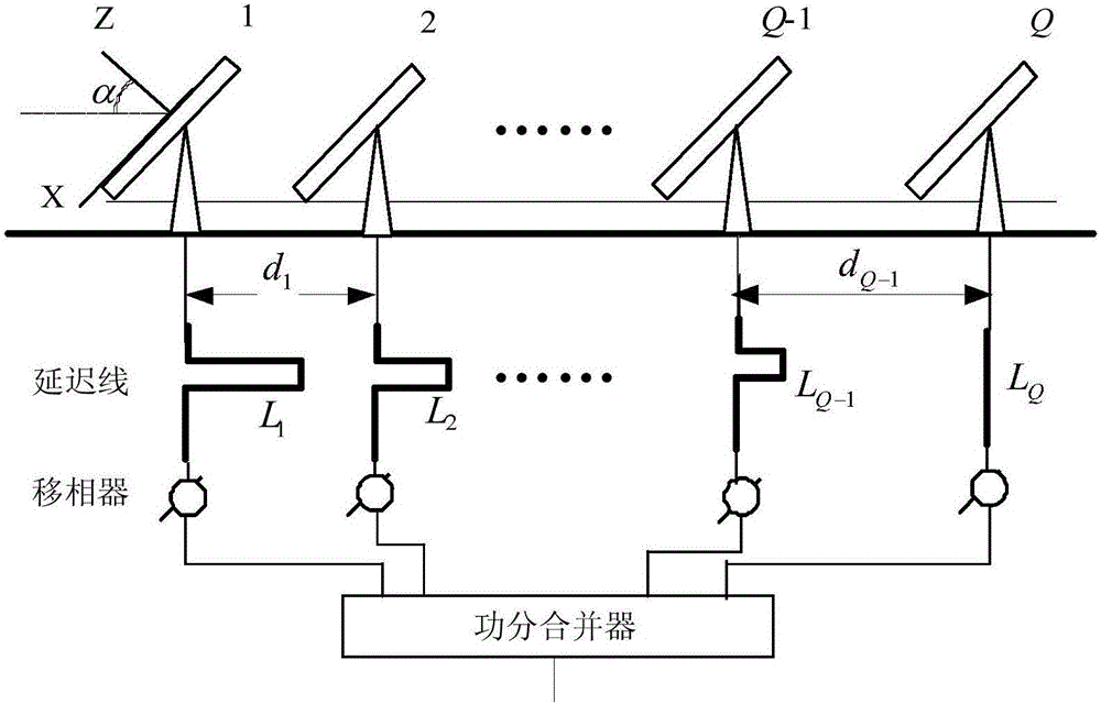
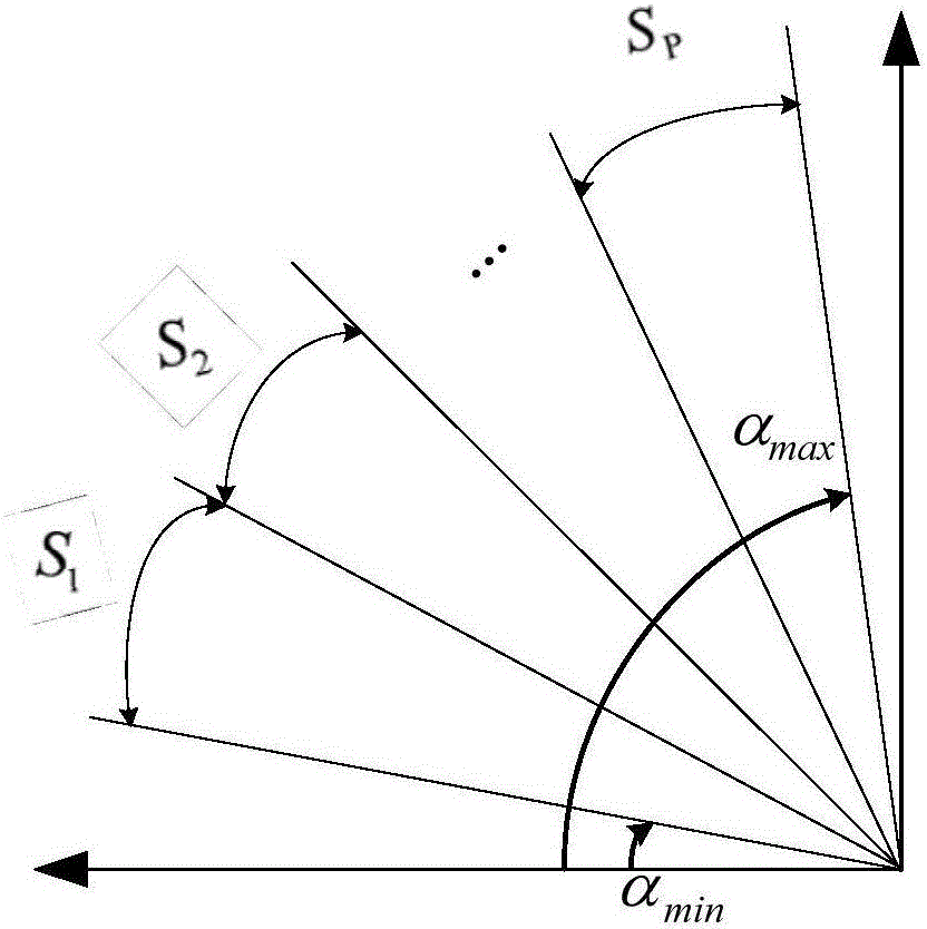
[0041] refer to figure 1 , the multi-subarray antenna beam switching method based on the maximum received signal power of the present invention comprises the following steps:

[0042] 1) The frequency of the received signal of the multi-subarray antenna is from f 0 become f 1 When , the array factor pattern model of the multi-subarray phased array antenna is established

[0043] 2) When the array factor of the multi-subarray phased array antenna is uniformly irradiated, when the last subarray in the multi-subarray phased array antenna is used as the phase reference, the array factor pattern of the subarray phased array antenna is obtained in the direction of the target satellite. Received signal strength in direction g(0,0,α,f 1 ), and then calculate the received signal power P(α,f 1 )=g(0,0,α,f 1 ) 2 ;

[0044] 3) Use a single set of delay lines to design th...


PUM


Abstract

The invention discloses a multi-sub-array antenna beam switching method based on maximization of power of a receiving signal. The method comprises the following steps of 1, establishing an array factor directional diagram model of a multi-sub-array phased array antenna; 2, acquiring strength g (0, 0, alpha, f1) of the receiving signal of an array factor directional diagram of the sub-array phased array antennas in a target satellite direction, and then computing power of the receiving signal of the array factor; 3, establishing an optimization model maxS by taking the maximal power P (alpha, f1, L) of the receiving signal after compensation of a delay line as a target and using the length of each sub-array delay line as a variable, and thus acquiring the length Lq of each sub-array delay line and a corresponding elevation angle beta aiming a satellite when compensation is performed by the delay line; and 4, computing a value of an elevation angle [alpha]n of each partition node, and then implementing multi-sub-array antenna beam switching according to the length Lq of each sub-array delay line, the corresponding elevation angle beta aiming the satellite when compensation is performed by the delay line and the value of the elevation angle [alpha]n of the partition node. According to the method of the invention, a delay error is compensated by the delay line, occurrence of the problem that the power of the receiving signal of the antenna is reduced caused by frequency variation is inhibited, and the cost is low.

Description

technical field [0001] The invention belongs to the technical field of satellite communication system antenna beam control, and relates to a multi-subarray antenna beam switching method based on maximization of received signal power. Background technique [0002] With the progress of the times and the development of science and technology, satellite communication technology has been widely used in the military and civilian fields. Mobile satellite communication technology has become an effective means of broadband mobile communication. Areas such as delivery play an important role. [0003] Multi-subarray technology can effectively reduce the antenna height and system cost, while taking into account the antenna performance, and is currently the most commonly used method for low-profile antennas. When receiving satellite signals, multi-subarray phased array antennas often need to receive beacons and carriers at the same time, and the frequency gap between the two may be larg...

Claims


Application Information

Patent Timeline
IPC IPC(8): H04B7/185H04B7/06H04B7/08
CPCH04B7/0602H04B7/0805H04B7/18578Y02D30/70
Inventor 姚敏立贾维敏于强戴定成林志强井亚鹊
Owner 中国人民解放军火箭军工程大学
Learn More