Air pressure type additive manufacturing spray head

An additive manufacturing and air pressure technology, applied in the field of fused deposition forming and air pressure additive manufacturing nozzles, can solve the problems of uneven thermal conductivity melting state, easy aging of edge materials, low material melting efficiency, etc., to solve the problem of melting state Non-uniformity, shorten the time required for heating, increase the heating speed and the effect of

Active Publication Date: 2016-12-14
NORTHWESTERN POLYTECHNICAL UNIV
View PDF8 Cites 6 Cited by
  • Summary
  • Abstract
  • Description
  • Claims
  • Application Information

AI Technical Summary

Problems solved by technology

[0003] Pneumatic fused deposition forming equipment, due to its advantages of simple equipment structure, unrestricted shape of consumables, and light nozzle, has received extensive attention in scientific research and practical applications. There are defects in the heating method, air pressure stability, etc., which limit its application to a certain extent.
[0004] There are mainly the following defects in the prior art: 1. The cavity space of the nozzle is too small, resulting in the problem that the amount of material available for molding is too small; 2. Due to the limitation of the thermal conductivity of the material, relyi

Method used


Image

  • Air pressure type additive manufacturing spray head
  • Air pressure type additive manufacturing spray head
  • Air pressure type additive manufacturing spray head

Examples


Embodiment Construction

[0025] The present invention will be further described in detail below in conjunction with specific embodiments, which are explanations of the present invention rather than limitations.

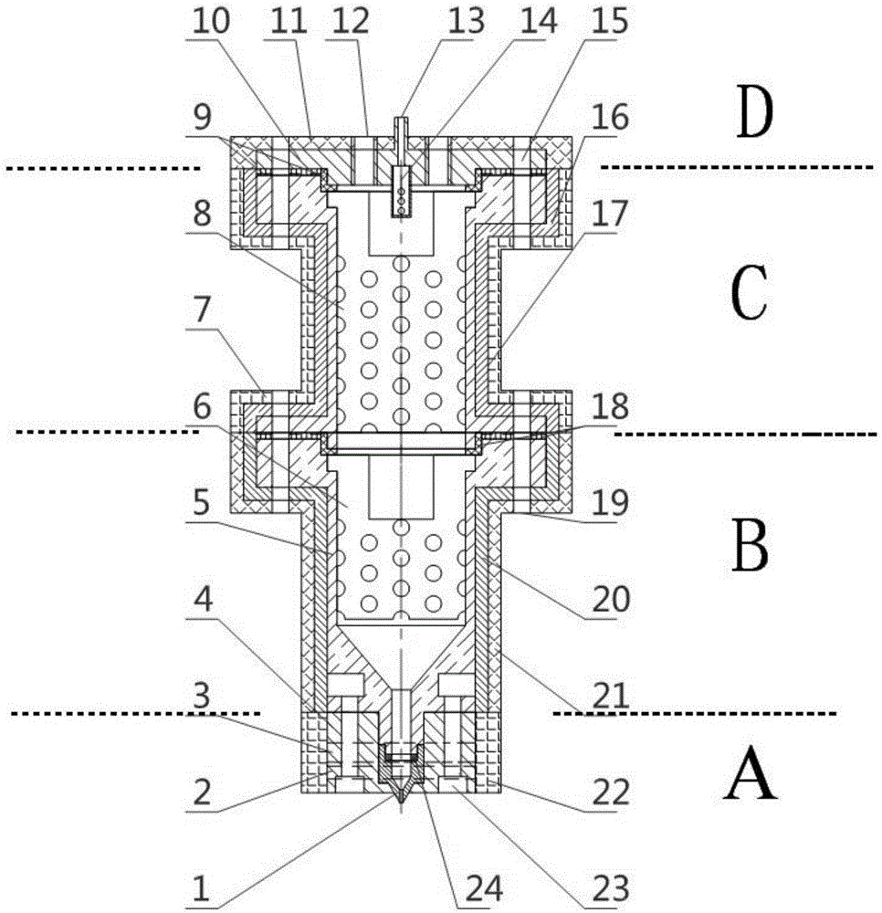
[0026] The present invention is a pneumatic additive manufacturing nozzle, such as figure 1 As shown, by adopting a multi-stage heating structure, heat insulating gaskets are arranged between each stage to reduce the mutual interference of the temperature field between the stages, so as to achieve the purpose of precise temperature control. Since the temperature field of each level is independently controlled, and each level is connected by bolts that are easy to install and disassemble, the number of heating levels can be increased or decreased according to the actual situation in the actual implementation process.

[0027] This preferred example is described by taking a two-stage barrel as an example. In terms of heating system: nozzle temperature measurement unit 2 and nozzle heating unit...


PUM


Abstract

The invention discloses an air pressure type additive manufacturing spray head. The air pressure type additive manufacturing spray head comprises a nozzle and multiple stages of storage barrels sequentially connected to the input end of the nozzle. A nozzle heating unit and a nozzle heat insulation layer are sequentially arranged on the outer portion of the nozzle. A nozzle gasket is arranged between the nozzle and the connected barrels. Each stage of barrel is sleeved with an independent barrel temperature control unit. Heating cavities in all the stages of barrel temperature control units are sequentially connected together in series in the axial direction. A barrel heat insulation layer is arranged on the outer portion of each barrel temperature control unit. A material heat conduction unit is arranged in each stage of barrel. Each material heat conduction unit comprises a plurality of heat conduction plates evenly arranged in the corresponding barrel. Barrel gaskets are arranged between the adjacent barrels. The feeding end of the last stage of barrel far away from the nozzle is sequentially provided with the corresponding barrel gasket, a barrel upper cover and a barrel upper cover heat insulation layer. Each barrel upper cover is provided with a feeding and extrusion force stabilization device connector and an extrusion force control connector. The barrel upper cover heat insulation layers, the barrel heat insulation layers of all the stages of barrels and the primary nozzle heat insulation layer are connected into a whole in a sealed manner.

Description

technical field [0001] The invention belongs to the field of additive manufacturing (3D printing) material processing, relates to fusion deposition forming technology, and specifically relates to a pneumatic additive manufacturing nozzle. Background technique [0002] Fused deposition modeling (FDM) is a relatively mature technology in the field of rapid prototyping. Its basic forming principle is to transform complex three-dimensional processing into simple two-dimensional plane processing, that is, by three-dimensional modeling software or three-dimensional scanner, etc. The 3D model of the part obtained by the tool is input to the pre-processing software to obtain the program to control the forming of the part. Under the control of the numerical control system, the molten material is extruded through the nozzle as required, from points and lines, to surfaces, and finally into a body. Reverse to obtain the desired shaped parts. [0003] Pneumatic fused deposition forming ...

Claims


Application Information

Patent Timeline
IPC IPC(8): B29C67/00B33Y30/00
CPCB33Y30/00
Inventor 刘建睿徐天文陈超黄卫东
Owner NORTHWESTERN POLYTECHNICAL UNIV
Why Eureka
Try Eureka