Pneumatic clamping device for workpieces

A pneumatic clamping and workpiece technology, applied in the direction of manufacturing tools, stamping machines, presses, etc., can solve the problems of structural and functional limitations, equipment can not be completed, complex operation of equipment, etc., to achieve high production efficiency, fast action, simple operation Effect

Active Publication Date: 2017-11-10
ZHEJIANG TIANCHENG SEAT
View PDF11 Cites 0 Cited by
  • Summary
  • Abstract
  • Description
  • Claims
  • Application Information

AI Technical Summary

Problems solved by technology

[0002] At present, the shortcomings of the equipment for pressing, pressing, and flanging of thin-walled parts are as follows: first, due to the limitation of structure and function, the selected equipment cannot complete the above tasks; Complicated operation, slow movement and low production efficiency

Method used


Image

  • Pneumatic clamping device for workpieces
  • Pneumatic clamping device for workpieces
  • Pneumatic clamping device for workpieces

Examples


Embodiment Construction

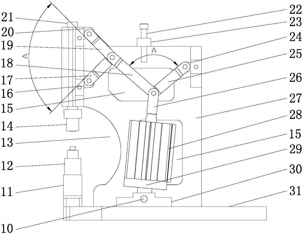
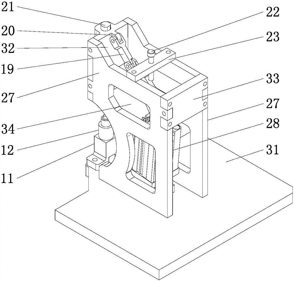
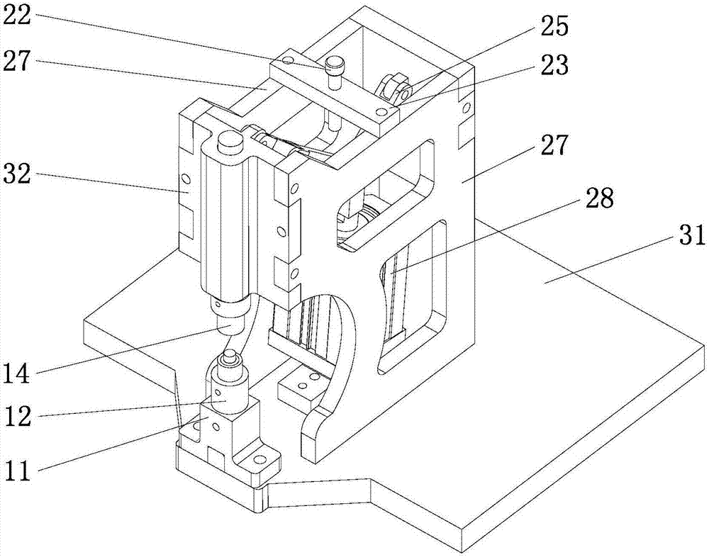
[0023] Below in conjunction with accompanying drawing, the present invention will be further described with specific embodiment, see figure 1 — Figure 6 :

[0024] The pneumatic clamping device of the workpiece includes a frame with a base 31, one end of the cylinder 28 is hinged on the base 31, and the other end is hinged with one end of the first connecting rod 25 and the second connecting rod 18 at the same time, and the first connecting rod 25 The other end of the second link 18 is hinged on the rear wall 33 of the frame, and the other end of the second link 18 is hinged with one end of the third link 19 and the fourth link 17 at the same time, and the other end of the third link 19 is hinged on the frame. On the front wall 32 of the front wall 32 of the rack, the vertical slideway 41 of the front wall 32 of the frame slides to be provided with a slide bar 21, and the lower end of the slide bar 21 is fixed with an upper module 14, and on the base 31 directly below the up...


PUM


Abstract

The invention belongs to the technical field of workpiece clamps and relates to a pneumatic clamping device for a workpiece. The device comprises a frame with a base, wherein one end of an air cylinder is hinged to the base while the other end of the air cylinder is hinged to one ends of first and second connecting rods simultaneously; the other end of the first connecting rod is hinged to the back wall of the frame while the other end of the second connecting rod is hinged to one ends of third and fourth connecting rods simultaneously; the other end of the third connecting rod is hinged to the front wall of the frame, a slide rod is slidably arranged on a vertical slideway in the front wall of the frame, an upper module is fixed at the lower end of the slide rod, a lower module is arranged on the base below the upper module, and the other end of the fourth connecting rod is hinged to the slide rod; a piston rod of the air cylinder retracts to drive the slide rod to move upward, so that both the first and second connecting rods and the third and fourth connecting rods form V-shaped included angles; and the piston rod of the air cylinder stretches out to drive the slide rod to move downward, so that the V-shaped included angles of both the first and second connecting rods and the third and fourth connecting rods are increased. The pneumatic clamping device for the workpiece has the advantages that the locking force is great, return can be stopped, and the device is used for machining a shaft pin and a thin-walled workpiece.

Description

technical field [0001] The invention belongs to the technical field of workpiece fixtures, in particular to a pneumatic clamping device for workpieces. Background technique [0002] At present, the shortcomings of the equipment for pressing, pressing, and flanging of thin-walled parts are as follows: first, due to the limitation of structure and function, the selected equipment cannot complete the above tasks; The operation is complicated, the action is slow, and the production efficiency is low. Contents of the invention [0003] The object of the present invention is to provide a pneumatic clamping device for workpieces with high production efficiency and multiple functions. [0004] The purpose of the present invention is achieved like this: [0005] Pneumatic clamping device for the workpiece, including a frame with a base, one end of the cylinder is hinged on the base, the other end is hinged with the first connecting rod and one end of the second connecting rod at ...

Claims


Application Information

Patent Timeline
Patent Type & Authority Patents(China)
IPC IPC(8): B30B1/08
CPCB30B1/08
Inventor 陈式烧牛德林
Owner ZHEJIANG TIANCHENG SEAT
Why Eureka
Try Eureka