
Low noise self-priming compound pump

A compound pump, low-noise technology, applied in the direction of pump, drive pump, pump components, etc., can solve the problem of fluid flow into the split pressure water chamber is not smooth, high operating noise, etc., to solve the problem of flow noise and flow loss, pump body Weight reduction and compact structure

Active Publication Date: 2017-11-03
ZHEJIANG SINCONTROL PUMP IND
View PDF4 Cites 0 Cited by
  • Summary
  • Abstract
  • Description
  • Claims
  • Application Information

AI Technical Summary

Problems solved by technology

[0006] Aiming at the disadvantages of the existing jet pumps such as high operating noise and unsmooth flow of fluid entering the split pressure water chamber, the purpose of the present invention is to provide a centrifugal pump with remarkable noise reduction effect, comprehensive working performance such as flow rate, lift and suction lift, and high feasibility. jet compound pump

Method used


Image

  • Low noise self-priming compound pump
  • Low noise self-priming compound pump
  • Low noise self-priming compound pump

Examples


Embodiment

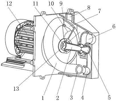
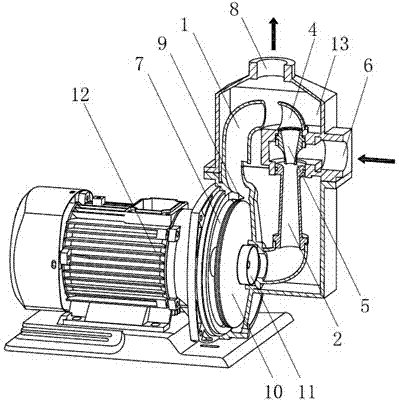
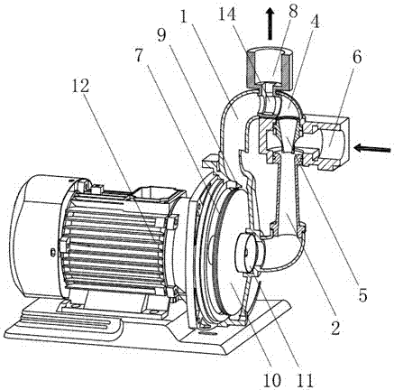
[0030] Embodiment: When the low-noise self-priming compound pump of this embodiment is working, a part of the fluid in the centrifugal volute chamber 7 of the compound pump is driven by the high-speed rotation of the centrifugal impeller 10, and after obtaining kinetic energy, it passes through the centrifugal volute chamber tongue 9 under the action of centrifugal force. After passing through the single-entry flow channel 1, the diversion flows smoothly and smoothly into the diversion pressure water chamber 13 or the diversion tee 14, and quickly converts kinetic energy into pressure potential energy. Therefore avoid the collision of guide vane on the guide vane plate 15 of the traditional jet pump and centrifugal impeller 10, scrape and flow noise and the flow loss of high-speed fluid impact jet pump guide vane 16, jet pump guide disc 17, see Figure 4 . Part of the fluid (high speed or high pressure) entering the diversion pressurized water chamber 13 or the diversion tee 1...


PUM


Abstract

A low-noise, self-priming and composite pump. According to the low noise self-priming composite pump, a diffusion guide vane (16) and a guide disc (17) of a conventional self-priming jet pump are replaced with a high-hydraulic-performance and high-efficiency centrifugal vortex chamber (7) having a single separating tongue (9) and a single outlet or having multiple separating tongues (9) and multiple outlets. A single-inlet flow channel (1) is designed to reasonably guide a centrifugally accelerated fluid to a distribution pumping chamber (13) or a distribution tee joint (14), so that scraping between the guide vane (16) as well as the guide disc (17) and a centrifugal impeller (10), and the strong impact of a high speed fluid to the guide vane (16) and the guide disc (17) are fundamentally eliminated, transitional flow between the centrifugal vortex chamber (7) and the distribution pumping chamber (13) or the distribution tee joint (14) is more smooth, and flow loss and flow noise are smaller. The reasonable layout of the single-inlet flow channel (1) can ensure continuous supply of a working fluid in an inlet section of a nozzle, so that negative pressure is maintained to obtain a powerful self-priming capability. The structure is more compact due to replacement of the conventional large-volume distribution pumping chamber (13) with the distribution tee joint (14).

Description

technical field [0001] The invention relates to a centrifugal injection composite pump, in particular to a noise-reducing single-entry self-priming composite pump, which belongs to the field of fluid machinery. Background technique [0002] The pump is a general-purpose fluid machine with a large output and a wide range of uses, and has a huge demand for energy. It transfers the mechanical energy or other energy of the prime mover to the liquid, and increases the mechanical energy of the liquid, so as to achieve the purpose of conveying and pressurizing the liquid. Self-priming jet pump is also called jet pump (self-priming jet-pump). The jet pump has simple structure and reliable performance. Compared with the vortex pump, the jet pump has strong suction, stable self-priming, and high efficiency. It is a pump product with a large volume and a wide range. [0003] As early as the 1860s, German scholar Zeuner used the momentum theorem to establish the design theory of jet p...

Claims


Application Information

Patent Timeline
Patent Type & Authority Patents(China)
IPC IPC(8): F04D9/06F04D29/42
CPCF04D9/06
Inventor 凃程旭包福兵陈荣国颜正辉陈志平陈海林
Owner ZHEJIANG SINCONTROL PUMP IND
Learn More