Hydraulic valve with adjustable latch

A locking device, hydraulic technology, applied in the field of hydraulic valves, to achieve the effect of saving space

Active Publication Date: 2019-12-17
ROBERT BOSCH GMBH
View PDF13 Cites 0 Cited by
  • Summary
  • Abstract
  • Description
  • Claims
  • Application Information

AI Technical Summary

Problems solved by technology

The valve is also designed to be particularly simple

Method used


Image

  • Hydraulic valve with adjustable latch
  • Hydraulic valve with adjustable latch
  • Hydraulic valve with adjustable latch

Examples


Embodiment Construction

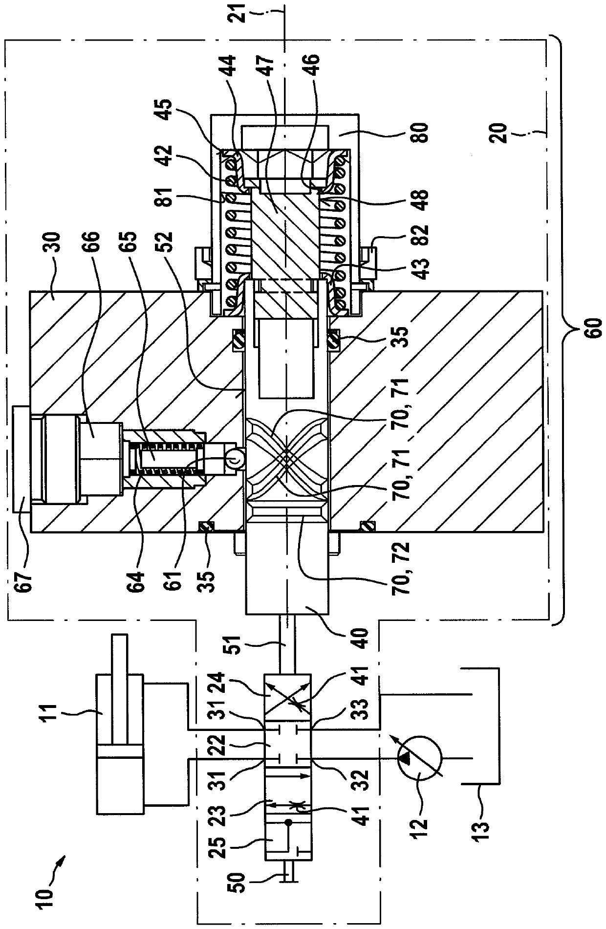
[0022] figure 1 The hydraulic drive system 10 is shown with a valve 20 according to a first embodiment of the invention. The drive system 10 includes an actuator 11 , which is designed, for example, as a hydraulic cylinder or a hydraulic motor, wherein the actuator is connected to two working connections 31 of the valve 20 . A pump 12 is further provided, which is connected to the pump connection 32 of the valve 20 . Furthermore, a tank 13 is provided, which is connected to the tank connection 33 of the valve 20 .

[0023] The valve 20 includes a locking device 60 , which is shown in detail, wherein the remaining valves are only shown symbolically. The corresponding transition points are marked with the reference numeral 51 . The valve 20 currently has four switching positions and can be used, for example, in agricultural tractors. In the blocking position 22 , all four connection points 31 ; 32 ; 33 are blocked, so that the actuator 11 is hydraulically clamped immovably. ...


PUM


Abstract

A hydraulic valve includes a sliding control member that delimits at least one constantly adjustable diaphragm. The sliding control member is configured to be moved in the direction of a longitudinal axis. The hydraulic valve further includes a locking device with a locking member that is configured to be moved counter to the force of a first spring transversely relative to the longitudinal axis. The hydraulic valve further includes at least one catch contour in which the locking member is configured to be engaged in such a positive-locking manner that the sliding control member is releasably retained in a catch position that is associated with the respective catch contour. The position of at least one catch contour is constantly adjustable in such a manner that the free cross-sectional surface-area of the at least one diaphragm is constantly adjustable in the associated catch position.

Description

technical field [0001] The invention relates to a hydraulic valve with a control slide movable in the direction of a longitudinal axis, the control slide delimiting at least one continuously adjustable flap, wherein a locking device is provided which has A locking body, which can be moved transversely to the longitudinal axis against the force of the first spring, wherein at least one locking contour is provided, in which the locking body can be locked positively in such a way that the control slide valve can be Releasably held in the latching position assigned to the associated latching contour. Background technique [0002] A hydraulic valve is known from DE 39 23 743 A1. The valve has a control slide movable in the direction of the longitudinal axis, the control slide defining a continuously adjustable flap. Furthermore, a locking device is provided, which has a locking body which can move transversely to the longitudinal axis against the force of the first spring. Fur...

Claims


Application Information

Patent Timeline
Patent Type & Authority Patents(China)
IPC IPC(8): F15B15/26F15B13/02
CPCF15B13/02F15B15/26F15B2015/268F16K31/1221F16K35/022F16K1/523F16K35/06
Inventor R.孔茨C.凯尔S.克纳佩尔
Owner ROBERT BOSCH GMBH
Why Eureka
Try Eureka