Control valve with flow limiting function

A technology for controlling valves and functions, applied in sliding valves, valve details, valve devices, etc., can solve the problems of inadequate overall operation, insufficient flow limitation, and insufficient flow limitation structure, etc., to achieve ideal flow limitation effect and improve work efficiency effect

Inactive Publication Date: 2016-12-14
JOHNSTON FLOW TECH WUXI CO LTD
View PDF7 Cites 1 Cited by
  • Summary
  • Abstract
  • Description
  • Claims
  • Application Information

AI Technical Summary

Problems solved by technology

[0002] The control valve consists of two main assemblies, the valve body assembly and the actuator assembly, which are divided into four series, single-seat series control valves, double-seat series control valves, sleeve series control valves and self-operated series control valves , the variants of the four types of valves can lead to many different applicable structures, each structure has its own special application, characteristics, advantages and disadvantages, although some control valves have wider application conditions than others, However, control valves are not suitable for all working conditions, so as to jointly build the best solution to enhance performance and reduce costs
[0003] Many control valves currently on the market have insufficient flow limiting structures, resulting in unsatisfactory flow limiting effects, resulting in inadequate overall operation, resulting in insufficient flow limiting, and reduced efficiency.

Method used


Image

  • Control valve with flow limiting function

Examples


Embodiment Construction

[0014] The following will clearly and completely describe the technical solutions in the embodiments of the present invention with reference to the accompanying drawings in the embodiments of the present invention. Obviously, the described embodiments are only some, not all, embodiments of the present invention. Based on the embodiments of the present invention, all other embodiments obtained by persons of ordinary skill in the art without making creative efforts belong to the protection scope of the present invention.

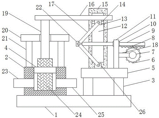
[0015] see figure 1 , the present invention provides a technical solution: a control valve with a flow limiting function, including a base plate 1, the top of the base plate 1 is provided with a valve seat 2 and a first support column 3 in sequence from left to right, and the first support column 3 The number is two, and the first support column 3 has played a supporting role. The two sides of the valve seat 2 are respectively clamped with an outlet pipe 23 an...


PUM


Abstract

The invention discloses a control valve with a flow limiting function. The control valve comprises a bottom plate. A valve seat and first supporting columns are sequentially arranged on the top of the bottom plate from left to right. A water outlet pipe and a water inlet pipe are clamped and connected to the two side faces of the valve seat correspondingly. Third supporting columns are fixedly connected to the two sides of the top of the valve seat. A sealing ring is arranged on the top of the valve seat. The tops of the third supporting columns are fixedly connected with a baffle. According to the control valve with the flow limiting function, the vertical movement of an adjusting valve is achieved through cooperative usage of connecting rods, a sliding rod, a motor, a gear and a gear rail, and therefore the flow limiting effect is achieved. The effect of connecting rod limiting is achieved through cooperative usage of a connecting plate, a limiting groove and a sliding block, and deflection cannot happen when the connecting rods drive a connecting beam to move up and down. The control valve is ideal in flow limiting effect, and the work efficiency is improved.

Description

technical field [0001] The invention relates to the technical field of control valves, in particular to a control valve with a flow limiting function. Background technique [0002] The control valve consists of two main assemblies, the valve body assembly and the actuator assembly, which are divided into four series, single-seat series control valves, double-seat series control valves, sleeve series control valves and self-operated series control valves , the variants of the four types of valves can lead to many different applicable structures, each structure has its own special application, characteristics, advantages and disadvantages, although some control valves have wider application conditions than others, However, control valves are not suitable for all working conditions, so we can jointly build the best solution to enhance performance and reduce costs. [0003] Many regulating valves currently on the market have insufficient flow limiting structures, resulting in u...

Claims


Application Information

Patent Timeline
IPC IPC(8): F16K3/02F16K31/04F16K31/54
CPCF16K3/0281F16K31/047F16K31/54
Inventor 钱向阳
Owner JOHNSTON FLOW TECH WUXI CO LTD
Why Eureka
Try Eureka