Cylindrical shell section regenerative electric heat storage device and heating method

A regenerative, electric thermal storage technology, applied in thermal storage heaters, thermal storage equipment, fluid heaters, etc., can solve problems such as electric energy waste

Inactive Publication Date: 2016-12-14
孙天泰
View PDF6 Cites 1 Cited by
  • Summary
  • Abstract
  • Description
  • Claims
  • Application Information

AI Technical Summary

Problems solved by technology

[0006] According to the above-mentioned technical problems, a tube-section regenerative electric heat storage device and heating method a

Method used


Image

  • Cylindrical shell section regenerative electric heat storage device and heating method
  • Cylindrical shell section regenerative electric heat storage device and heating method
  • Cylindrical shell section regenerative electric heat storage device and heating method

Examples


Embodiment 1

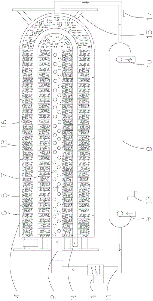
[0031] Example 1, such as figure 1 and figure 2 As shown in the figure, a tube-section heat storage electric heat storage device includes a hot air pipe I11 and a hot air blower I1 arranged on the hot air pipe I11, and the output end of the hot air pipe I11 is connected to the input end of the air pipe I2 , blow the air in the hot air pipe I11 into the air pipe I2.

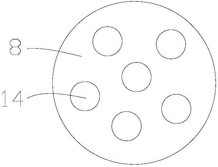
[0032] The air duct I2 is arranged at the center of the heat storage cylinder 4, and the outer wall of the air duct I2 inside the heat storage cylinder 4 has an air duct hole I7, so that air can enter other spaces of the heat storage cylinder 4 through the air duct hole I7.

[0033] The hot air pipe I11 communicates with the air pipe I2 and the heat storage cylinder 4 provided with one. The heat storage cylinder 4 is carried on the bracket I15.

[0034] The inside of the heat storage cylinder 4 is provided with a heating pipe I3, and the heating pipe I3 ​​is arranged in a circumferential direction on the outer...

Embodiment 2

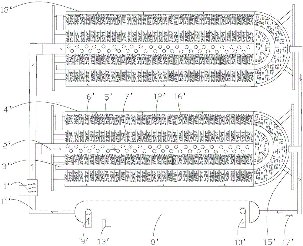
[0048] Example 2, such as image 3 and Figure 4 As shown, a tube-section heat storage electric heat storage device includes a heat storage cylinder, a hot air pipe II11' and a hot air blower II1' arranged on the hot air pipe II11', and the heat storage cylinder is provided with two , are respectively the first heat storage cylinder 4' and the second heat storage cylinder 18'. The first heat storage cylinder 4' and the second heat storage cylinder 18' are carried on the support II 15'.

[0049] The first heat storage cylinder 4' and the second heat storage cylinder 18' are the same heat storage mechanism, and the hot air pipe II11' is the same as the first heat storage cylinder 4' and the second heat storage cylinder 18' respectively. connected.

[0050] In the first heat storage cylinder 4', the output end of the hot air pipe II11' is connected with the input end of the air pipe II2', and the air in the hot air pipe II11' is blown into the air pipe II2'.

[0051] The air ...


PUM


Abstract

The invention discloses a cylindrical shell section regenerative electric heat storage device and a heating method. The cylindrical shell section regenerative electric heat storage device comprises a hot air duct and a hot air blower arranged on the hot air duct, wherein the output end of the hot air duct is connected with the input ends of one or more air ducts; the air ducts are arranged at the centers of one or more heat storage cylinders; air duct holes are formed in the outer walls of the air ducts inside the heat storage cylinders; and the air ducts and the heat storage cylinders communicate with the hot air duct. According to the cylindrical shell section regenerative electric heat storage device and the heating method disclosed by the invention, a heating pipe and heat storage solid particles are arranged; during the valley time period, the heat storage solid particles are heated by the heating pipe, and electric energy is converted into heat energy for storage; and when needing to use, the heat energy stored by the heat storage solid particles is exported through the space where air flows through the heat storage solid particles, a water source in convection pipes is heated, the heat energy of the hot air is transferred to the water source in the convection pipes, and then the heated water source is outputted, thereby achieving the advantage that electric heat storage can be performed during the valley time period, and the stored heat energy can be exported for utilization during other time periods.

Description

technical field [0001] The invention relates to a tube-section heat storage type electric heat storage device and a heating method. Background technique [0002] At present, valley electricity is based on the spirit of the document jointly issued by the Electricity Industry Bureau of the Economic and Trade Committee of the Price Bureau. The peak and valley electricity used by residents is a new type of electricity price that is currently being piloted among urban residents. [0003] It divides 24 hours a day into two time periods. The 14 hours from 8:00 to 22:00 are called the peak period, and the peak electricity price is 0.56 yuan / kWh; there are 10 periods from 22:00 to 8:00 the next day The hour is called the valley section, and the implementation valley electricity price is 0.28 yuan kWh. [0004] Moreover, the blue sky project launched by the state now advocates reducing the use of coal and reducing the generation of smog. Therefore, small coal-fired boilers will be gr...

Claims


Application Information

Patent Timeline
IPC IPC(8): F24H7/04F24H9/18F24H9/00F28D20/00
CPCF24H7/0416F24H9/00F24H9/18F24H2250/02F28D20/0056Y02E60/14
Inventor 孙天泰
Owner 孙天泰
Why Eureka
Try Eureka