Connecting wire device of wire-changing power strip

A connection line and wireless plug-in technology, which is applied to the parts, connections, coupling devices, etc. of the connection device, can solve the problems of long lines, damage to the plug-in strip, and failure to restore the original state, etc., to achieve friendly application environment, convenient installation and use, The effect of a broad market prospect

Inactive Publication Date: 2016-12-14
QINGDAO UNIV
View PDF6 Cites 3 Cited by
  • Summary
  • Abstract
  • Description
  • Claims
  • Application Information

AI Technical Summary

Problems solved by technology

However, in the existing sockets on the market, it is impossible to quickly replace the socket cables. The wiring of the row is connected, and the main structure of the plug-in row must be disassembled to disassemble and replace the connecting line of the plug-in row. Moreover, the manufacturing process and technical level of the plug-in row at this stage are becoming more and more high-tech, and disassembling the main structure of the plug-in row is easy to cause It cannot be restored to its original state, causing damage to the socket
At present, the plug-in strips sold are all fixed-size connecting cables, and the specifications of the plug-in connecting cables are generally only 5m, 10m, 15m, 20m and other specifications. This kind of plug-in strip with fixed-size plug-in cables is difficult to meet flexibility , Diversified market demand, and the size difference is too large, which will bring a lot of inconvenience in life, such as the connection line is not long enough when using one plug-in strip, and the line is too long when two plug-in strips are used in series. If you want the length of the connecting wire to be appropriate, you can only use destructive means to cut off the connecting wire and connect it to the connecting wire. However, this method is dangerous and can easily cause hidden dangers.

Method used


Image

  • Connecting wire device of wire-changing power strip
  • Connecting wire device of wire-changing power strip
  • Connecting wire device of wire-changing power strip

Examples


Embodiment

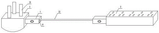
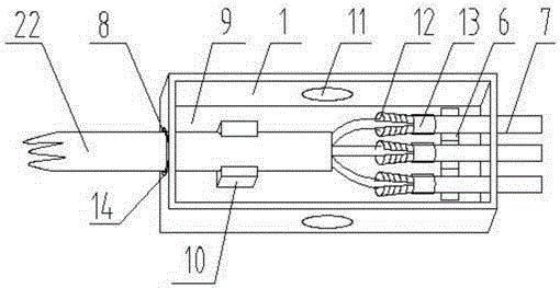
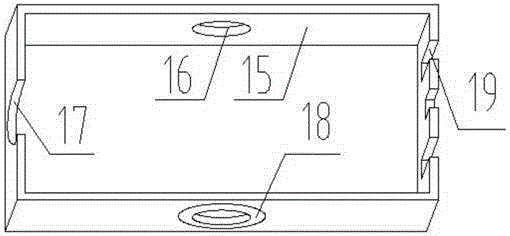
[0017]The main structure of the connecting line device related to the present embodiment includes: a connecting plug 1, a wireless socket 2, a wireless socket 3, a first connecting jack 4, a second connecting jack 5 and a connecting wire 22; the connecting plug The main structure of 1 includes: pin support seat 6, pin 7, wire inlet hole 8, box body 9, fixing block 10, bump 11, fixing piece 12, fixing bolt 13, T-shaped sealing rubber sleeve 14, box cover 15 , bump fixing hole 16, U-shaped groove 17, sealing rubber sleeve 18, latch groove 19 and pull button 20, the cuboid box body 9 of engineering plastic material with high temperature resistance and high flame retardancy is a pentahedron structure with an opening on the top surface, two Protrusions 11 are respectively placed at the center of the long sides, and the protrusions 11 are round cap-shaped structures protruding outwards. The latch 7 is made up of three elongated metal strips that pass horizontally through the right si...


PUM


Abstract

The present invention belongs to the electric appliance equipment technology field, and relates to a connecting wire device of a wire-changing power strip. The main body structure of the connecting wire device comprises connecting plugs, a wireless power strip, a wireless socket, a first connecting jack, a second connecting jack and a connecting wire, and the main body structure of each connecting plug comprises a plug supporting base, a plug, a box body, a fixing bolt, a T-shaped sealant sleeve, a box cover, a bump fixing hole, a U-shaped groove, a sealant sleeve, a plug groove, a pull buckle, etc. The connecting plugs are arranged at the two ends of the connecting wire, the first connecting jack on the side surface of the wireless power strip is in inserted connection with the connecting plug at one end of the connecting wire, and the connecting plug at the other end of the connecting wire is in inserted connection with the second connecting jack on the front side surface of the wireless socket. By just plugging the connecting plugs out of the wireless power strip and the wireless socket, and opening the box cover, the connecting wire of any length is disassembled and replaced. The connecting wire device is simple in main body structure, good in safety and friendly in application environment, is convenient to install and use, and possesses a good market application prospect.

Description

Technical field: [0001] The invention belongs to the technical field of electrical equipment, and relates to a connecting wire device, in particular to a connecting wire device for changing wires and inserting rows. According to actual needs, a suitable length of the connecting wire is selected, and plugs are directly installed at both ends of the connecting wire, and one end of the connecting wire is The plug on the side of the wireless strip is inserted into the jack on the side of the wireless strip, and the plug on the other end is inserted into the wireless socket to complete the socket change. Background technique: [0002] Nowadays, our country has already entered the era of electrification. Electric energy is closely related to the daily life of each of us and is inseparable, and the transmission of electric energy is inseparable from transmission lines. Especially in family life, in order to transmit power to various electrical appliances, various sockets are connec...

Claims


Application Information

Patent Timeline
Patent Type & Authority Applications(China)
IPC IPC(8): H01R31/06H01R13/506H01R4/32
CPCH01R4/32H01R13/506H01R31/06
Inventor 于正河石云鹏于希萌蔡冬马文静
Owner QINGDAO UNIV
Why Eureka
Try Eureka