Switching method of terminal antenna, device and mobile terminal

A technology of terminal antenna and switching device, applied in the field of communication, can solve the problems of difficult coverage, limited bandwidth of terminal antenna, poor signal, etc., and achieve the effect of improving the transmission and reception capabilities

Active Publication Date: 2016-12-14
GUANGDONG OPPO MOBILE TELECOMM CORP LTD
View PDF4 Cites 13 Cited by
  • Summary
  • Abstract
  • Description
  • Claims
  • Application Information

AI Technical Summary

Problems solved by technology

However, due to the increasing number of various hardware integrated in the terminal and the thinner and thinner design of the terminal, the space allocated to the terminal antenna is very limited.
In this case, the bandwidth that the terminal antenna can cover is also limited, especially it is difficult to cover the lower frequency band or the signal received by the lower frequency band is poor.

Method used


Image

  • Switching method of terminal antenna, device and mobile terminal
  • Switching method of terminal antenna, device and mobile terminal
  • Switching method of terminal antenna, device and mobile terminal

Examples


no. 1 example

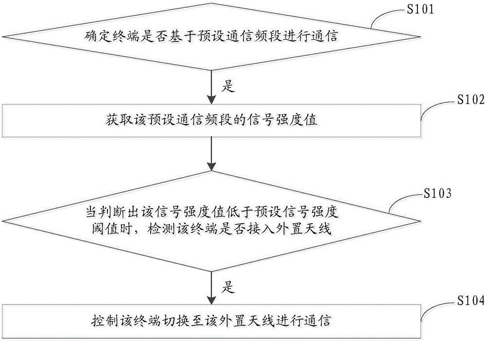
[0028] A method for switching antennas of a terminal, comprising: determining whether a terminal communicates based on a preset communication frequency band; if it is determined that the terminal communicates based on a preset communication frequency band, acquiring a signal strength value of the preset communication frequency band; When the strength value is lower than the preset signal strength threshold, it is detected whether the terminal is connected to the external antenna; if it is detected that the terminal is connected to the external antenna, the terminal is controlled to switch to the external antenna for communication.

[0029] see figure 1 , figure 1 It is a schematic flow diagram of the terminal antenna switching method provided in the first embodiment of the present invention, and the specific flow may include:

[0030] In step S101, it is determined whether the terminal performs communication based on a preset communication frequency band.

[0031] It can be ...

no. 2 example

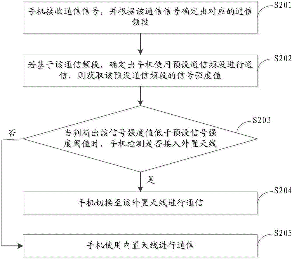
[0065] According to the method described in the first embodiment, a mobile phone is taken as an example below to further describe the terminal antenna switching method in detail.

[0066] see figure 2 , figure 2 It is a schematic flow diagram of the terminal antenna switching method provided in the second embodiment of the present invention, and the specific flow may include:

[0067] In step S201, the mobile phone receives a communication signal, and determines a corresponding communication frequency band according to the communication signal.

[0068] For example, due to reasons such as the design of the current mobile phone is becoming thinner and thinner, the space allocated to the antenna of the mobile phone is limited. In this case, the frequency band that the antenna of the mobile phone can cover is also limited, which leads to poor signal reception of some lower frequency bands received by the antenna.

[0069] In order to improve the mobile phone's ability to rec...

no. 3 example

[0109] In order to facilitate better implementation of the terminal antenna switching method provided by the embodiment of the present invention, the embodiment of the present invention further provides a device based on the foregoing terminal antenna switching method. The meanings of the nouns are the same as those in the above terminal antenna switching method, and for specific implementation details, refer to the description in the method embodiments.

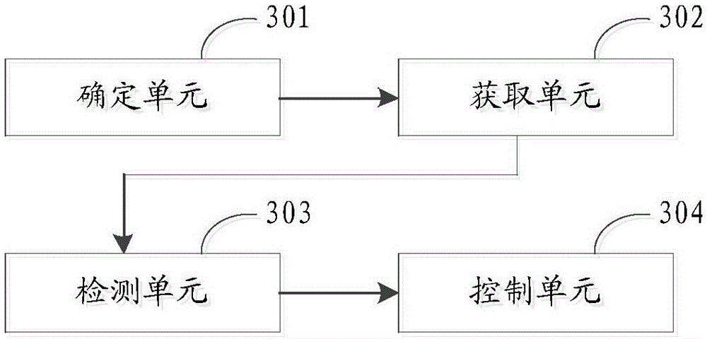
[0110] see Figure 3a , Figure 3a It is a schematic structural diagram of a terminal antenna switching device provided in the third embodiment of the present invention, and the device may include: a determination unit 301 , an acquisition unit 302 , a detection unit 303 , and a control unit 304 .

[0111] The determining unit 301 is configured to determine whether the terminal performs communication based on a preset communication frequency band.

[0112] For example, after the terminal receives a communication signal, th...


PUM


Abstract

The invention discloses a switching method of a terminal antenna, a device and a mobile terminal. The method comprises the following steps: determining whether a terminal communicates based on a preset communication frequency band; if determining that the terminal communicates based on the preset communication frequency band, acquiring a signal intensity value of the preset communication frequency band; when judging that the signal intensity value is less than a preset signal intensity threshold, detecting whether an external antenna is accessed into the terminal; if detecting that the external antenna is accessed into the terminal; controlling the terminal to switch to the external antenna to communicate. Therefore, the terminal is controlled to switch to the external antenna to communicate when a low-frequency band signal received by a built-in antenna of the terminal is bad. Since the frequency band range of the external antenna is wider than that of the built-in antenna of the terminal, and the performance of the external antenna is better than that of the built-in antenna, the terminal is controlled to switch to the external antenna to communicate, thereby effectively improving the transmitting-receiving capacity of the terminal to the low-frequency band signal.

Description

technical field [0001] The invention belongs to the technical field of communications, and in particular relates to a method and device for switching terminal antennas and a mobile terminal. Background technique [0002] With the continuous development of wireless communication technology, various new technologies are constantly emerging, such as carrier aggregation technology. Carrier aggregation technology can obtain larger transmission bandwidth by aggregating multiple continuous or non-consecutive component carriers, thereby obtaining higher peak rate and throughput. That is to say, through carrier aggregation technology, a higher data transmission rate can be achieved, enabling users to obtain more resources. [0003] However, when the carrier aggregation technology is applied, more and more signal frequency bands are used, which requires the bandwidth of the antenna of the terminal device to be large enough. However, because more and more various hardwares are integr...

Claims


Application Information

Patent Timeline
Patent Type & Authority Applications(China)
IPC IPC(8): H04B7/06H04B7/08
CPCH04B7/061H04B7/0814
Inventor 曾元清
Owner GUANGDONG OPPO MOBILE TELECOMM CORP LTD
Why Eureka
Try Eureka