
Artificial eyes and manufacture thereof

An eye, artificial technology, used in eye implants, other home appliances, prostheses, etc., can solve problems such as time-consuming

Inactive Publication Date: 2016-12-14
MANCHESTER METROPOLITAN UNIVERSITY
View PDF8 Cites 2 Cited by
  • Summary
  • Abstract
  • Description
  • Claims
  • Application Information

AI Technical Summary

Problems solved by technology

this is a time consuming process

Method used


Image

  • Artificial eyes and manufacture thereof
  • Artificial eyes and manufacture thereof
  • Artificial eyes and manufacture thereof

Examples


Embodiment Construction

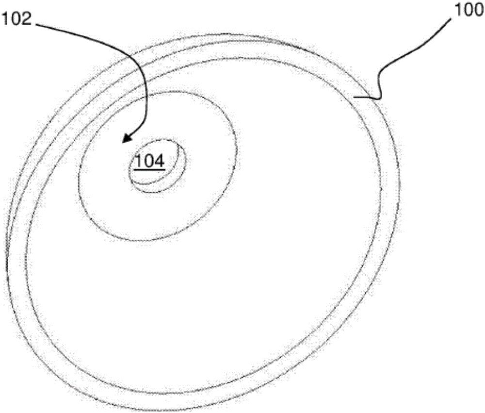
[0087] refer to Figure 16 , shows a method of manufacturing an artificial eye according to an embodiment of the present invention.

[0088] The first step in the method is to provide a substrate. The substrate can be formed by known methods, or alternatively, as discussed below, the substrate can be formed using 3D printing or dye sublimation methods.

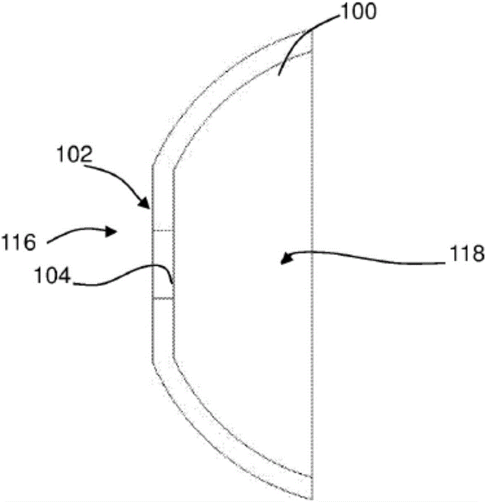
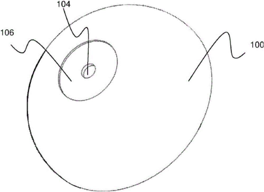
[0089] figure 1 and 2 The substrate 100 is shown in . In this embodiment, the substrate has a convex shape, in particular a hollow dome shape. The apex 102 of the dome is flat. A hole 104 is formed in the apex 102 of the substrate 100 and extends through the thickness of the substrate. In some embodiments, such as image 3 As shown in , a circular depression 106 may be formed around the hole 104 . In this embodiment, the substrate is about 1 mm thick.

[0090] In a next step S230, a support in the form of a pin is pushed through the hole in the base. image 3 A pin 108 used in one embodiment is shown in . The pin ha...


PUM


Abstract

A method of manufacturing an artificial eye for fitting as a whole or partial replacement of a patient's original eye. This is done by providing an image of an iris on a substrate (100, 300) comprising at least a frontal region of an artificial eye, providing a support (108, 308) for the substrate, positioning the substrate and support in a mould (122, 322), and encapsulating the substrate within a mould material (136, 336).

Description

technical field [0001] The present invention relates to an artificial eye (ocular prosthesis) and a method for its manufacture. Background technique [0002] Artificial eyes have been manufactured for centuries for patients whose eyes have been damaged by injury or disease. However, the techniques used still require specialized skills and are labor-intensive. Typically, prostheses are made of acrylic plastic, such as polymethylmethacrylate (PMMA), and are encapsulated. Prior to encapsulation, maxillofacial prosthetists and prosthetic eyemakers simulate iris and sclera colors using a personal hand-painting technique in the presence of the patient (or from an image of the patient's eye). Use a variety of artists media with pencils, crayons, cotton, or brushes. This technique requires inherent artistry and is time-consuming and expensive. Results depend on operator talent and experience. [0003] To encapsulate the artificial eye, a two-stage molding process is typically u...

Claims


Application Information

Patent Timeline
Patent Type & Authority Applications(China)
IPC IPC(8): B29D11/02B29C45/14
CPCB29L2011/0008B29C45/14065B29C45/14754B29D11/02B29C2045/14131B29C2045/14139B29C2045/1477A61F2230/0093A61F2240/001A61F2240/004A61F2/141B29C45/0001B29C45/14819B29K2233/12
Inventor 托马斯·乔治·弗瑞普路易斯·格林莱斯利·伊丽莎白·吉尔
Owner MANCHESTER METROPOLITAN UNIVERSITY
Learn More