
Antitheft clamping device applicable to display article

A clamping device and cover plate technology, which is applied in applications, household appliances, display stands, etc., can solve problems such as poor stability, and achieve the effects of stable clamping, flexible operation, and good clamping stability

Active Publication Date: 2016-12-21
HANGZHOU LANGHONG TECH
View PDF12 Cites 3 Cited by
  • Summary
  • Abstract
  • Description
  • Claims
  • Application Information

AI Technical Summary

Problems solved by technology

[0005] The purpose of the present invention is to overcome the disadvantages of poor stability and potential safety hazards in the mobile phone anti-theft connection method in the prior art, and to provide a stable clamping, versatile, flexible and convenient operation suitable for exhibits. Anti-theft clamping device

Method used


Image

  • Antitheft clamping device applicable to display article
  • Antitheft clamping device applicable to display article
  • Antitheft clamping device applicable to display article

Examples


Embodiment 1

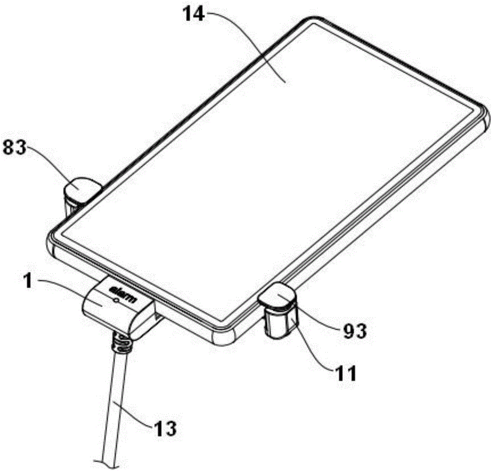
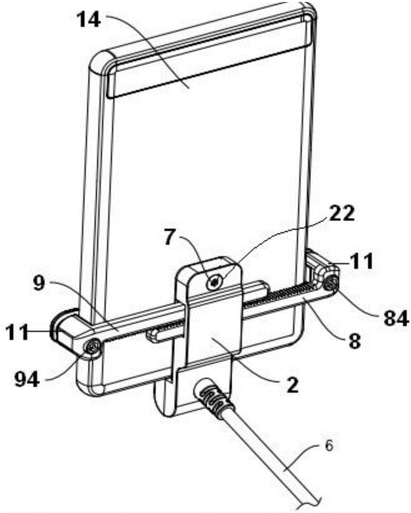
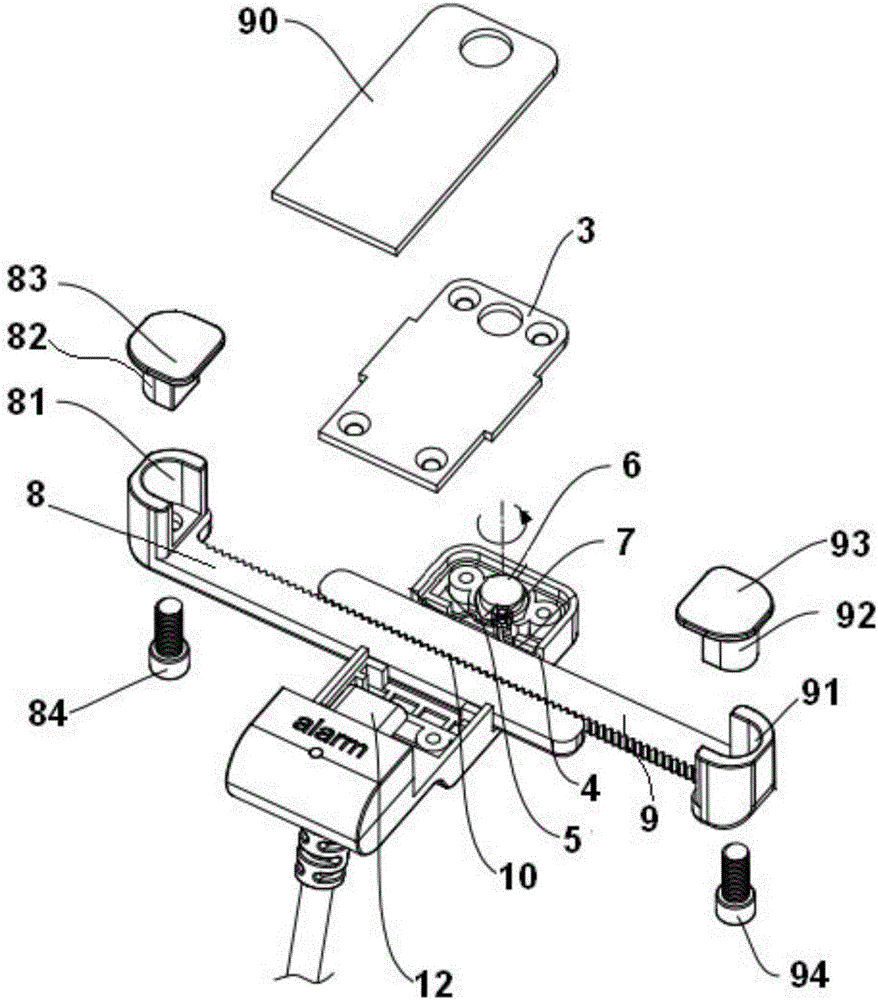
[0040] Such as figure 1 , figure 2 The shown embodiment is an anti-theft clamping device suitable for exhibits, including a fixed base 1, a lower cover 2 connected to the fixed base, an upper cover 3, a groove 4 on the lower cover, and a shrapnel 5 and the cam 6 for promoting the shrapnel;

[0041] The bottom of the cam is provided with an unlocking mechanism 7 that exposes the lower cover, and the groove is provided with a left tooth arm 8 and a right tooth arm 9 that are arranged in front and behind and intermeshing with each other. The vertical teeth 10, the cam and the shrapnel are in contact, the upper cover and the lower cover are detachably connected, and the left end of the left tooth arm and the right end of the right tooth arm are provided with a hook mechanism 11 for cooperating with the exhibit.

[0042] Such as image 3 As shown, the hook mechanism of the right tooth arm includes a right U-shaped groove plate 91 arranged on the right tooth arm, a right cylinde...

Embodiment 2

[0054] Embodiment 2 includes all structures in Embodiment 1, such as Figure 4 As shown, the left toothed arm and the right toothed arm of embodiment 2 are arranged up and down, and the lower cover is provided with a rack 21 meshing with the left toothed arm and the right toothed arm; the hook mechanism of the left toothed arm is curved to the right The left bending plate 85, the hook mechanism of the right toothed arm is the right bending plate 95 curved to the left.

[0055] There is a cavity extending along the left tooth arm in the left tooth arm, an air bag is arranged in the cavity, a pressure plate is arranged on the air bag, the pressure plate is connected with a push rod protruding from the cavity, and the air bag is connected with the left bend of the left tooth arm. Air cushion communication on the inner side of the panel;

[0056] There is a cavity extending along the right tooth arm in the right tooth arm, an air bag is arranged in the cavity, a pressing plate is...


PUM


Abstract

The invention discloses an antitheft clamping device applicable to a display article. The antitheft clamping device comprises a fixing seat, a lower cover plate, an upper cover plate, a groove, an elastic sheet and a cam, wherein the lower cover plate is connected with the fixing seat; the groove is formed in the lower cover plate; the cam is used for pushing the elastic sheet; the bottom of the cam is provided with an unlocking mechanism exposed out of the lower cover plate; a left tooth arm and a right tooth arm which are mutually engaged and are arranged at the front side and the back side are arranged in the groove; a plurality of vertical teeth are respectively arranged on the contact side surfaces of the left tooth arm and the right tooth arm; the cam is in contact with the elastic sheet; the upper cover plate and the lower cover plate are detachably connected; the left end of the left tooth arm and the right end of the right tooth arm are respectively provided with hook mechanisms matched with the display article. The antitheft clamping device has the characteristics that the connection fixation function is realized; the universality is high; the operation is flexible; convenience and high speed are realized; the clamping stability is high.

Description

technical field [0001] The invention relates to the technical field of commodity display anti-theft technology, in particular to an anti-theft clamping device suitable for exhibits with stable clamping, strong versatility, flexible operation and convenience. Background technique [0002] In the anti-theft field of commodity display, mobile phone anti-theft devices are used for anti-theft display in shopping malls, that is, when the anti-theft contacts of the mobile phone anti-theft device are disassembled, the mobile phone anti-theft device will trigger the alarm to sound an alarm to prompt that the mobile phone is at risk of being stolen. Some mobile phone anti-theft devices are mostly designed for electronic detection and anti-theft. This anti-theft method is intelligent and timely warning and reduces the risk of theft. It does not have anti-robbery protection and has a low safety factor. [0003] For some mobile phones with detachable back covers and replaceable batteries...

Claims


Application Information

Patent Timeline
Patent Type & Authority Applications(China)
IPC IPC(8): A47F7/024
CPCA47F7/0246
Inventor 忻宏
Owner HANGZHOU LANGHONG TECH
Features
  • Generate Ideas
  • Intellectual Property
  • Life Sciences
  • Materials
  • Tech Scout
  • Unparalleled Data Quality
  • Higher Quality Content
  • 60% Fewer Hallucinations
Learn More