A pipe double-end flare die

A double-end, pipe technology, applied in the field of flaring molds, can solve the problems of wasting time, troublesome single-end flaring, etc., and achieve the effects of convenient use, time-saving, convenient collection of pipes, and good clamping effect

Active Publication Date: 2018-08-03
JIANGSU HENGKANG ELECTRICAL
View PDF10 Cites 1 Cited by
  • Summary
  • Abstract
  • Description
  • Claims
  • Application Information

AI Technical Summary

Problems solved by technology

[0003] The purpose of the present invention is to provide a pipe double-end flaring die, which has the advantages of double-end flaring and solves the troublesome and time-wasting problems of single-end flaring

Method used


Image

  • A pipe double-end flare die
  • A pipe double-end flare die

Examples


Embodiment Construction

[0017] The following will clearly and completely describe the technical solutions in the embodiments of the present invention with reference to the accompanying drawings in the embodiments of the present invention. Obviously, the described embodiments are only some, not all, embodiments of the present invention. Based on the embodiments of the present invention, all other embodiments obtained by persons of ordinary skill in the art without making creative efforts belong to the protection scope of the present invention.

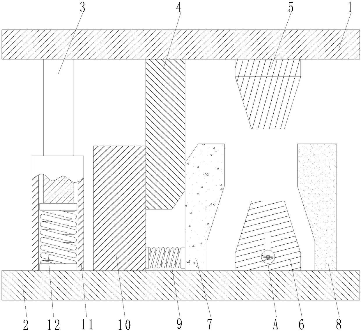
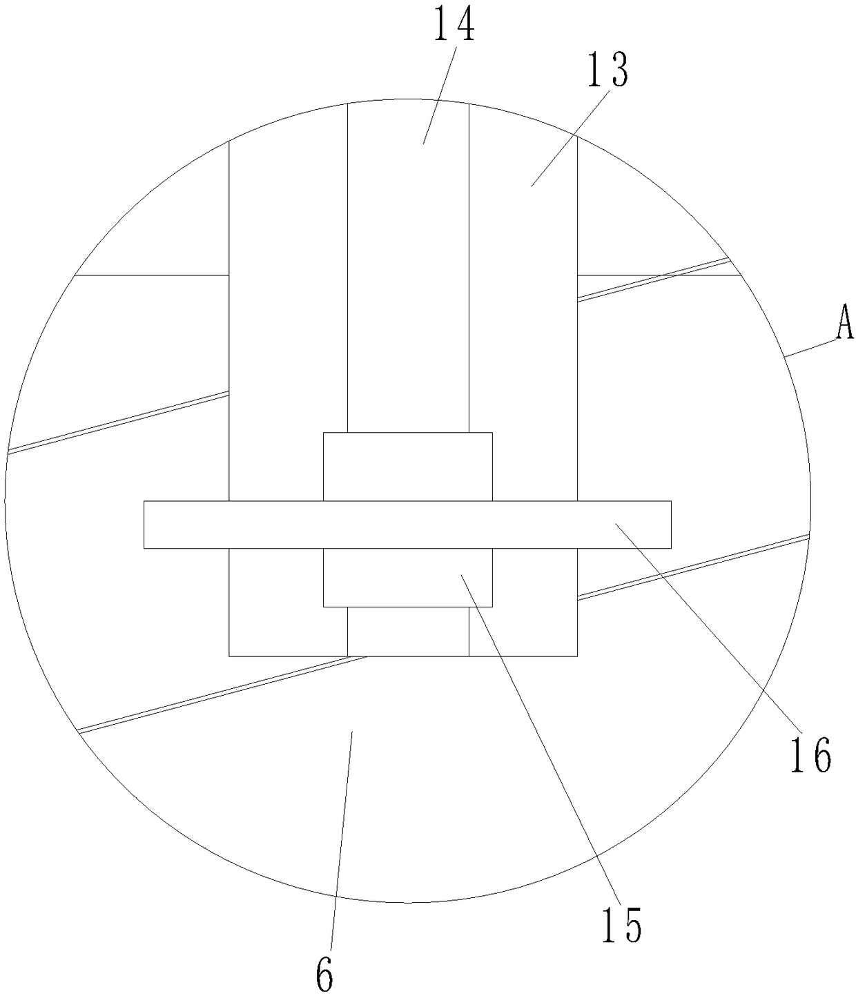
[0018] see Figure 1-2 , a pipe double-end flared die, including an upper template 1 and a lower template 2, the lower surface of the upper template 1 is fixedly connected with a guide rod 3, a wedge 4 and an upper punch 5 from left to right in sequence, by setting the wedge 4. When the wedge 4 is pressed down, the left movable splint 7 is moved to the right to clamp the pipe material. The upper punch 5 is symmetrically provided with the lower punch 6 correspo...


PUM


Abstract

The invention discloses a flaring mold for two ends of a pipe. The flaring mold comprises an upper mold plate and a lower mold plate. A guide rod, a tapered wedge and an upper convex mold are fixedly connected to the lower surface of the upper mold plate in sequence from left to right. A lower convex mold is symmetrically arranged at the position, corresponding to the upper convex mold, of the lower mold plate. A left movable clamp plate and a right movable clamp plate are arranged on the two sides of the lower convex mold correspondingly. The bottom of the left movable clamp plate and the bottom of the right movable clamp plate are both fixedly connected to the upper surface of the lower mold plate. The lower side of the side face, far away from the lower convex mold, of the left movable clamp plate is fixedly connected with one end of a first spring. According to the flaring mold, through the arrangement of the tapered wedge, when the tapered wedge is pressed, the left movable clamp plate moves rightwards, and the pipe is clamped; through the arrangement of a guide pipe and the guide rod, position shift cannot happen when the upper mold plate is pressed; through the arrangement of the upper convex mold, the lower convex mold, the left movable clamp plate and the right movable clamp plate, the effect of flaring the two ends of the pipe is achieved; and the two ends of the pipe are flared by the upper convex mold and the lower convex mold at the same time, and during use, greater convenience is achieved, and more time is saved.

Description

technical field [0001] The invention relates to the technical field of flaring dies, in particular to a pipe double-end flaring die. Background technique [0002] Molds are various molds and tools used in industrial production for injection molding, blow molding, extrusion, die-casting or forging forming, smelting and stamping to obtain the required products; in short, molds are tools used to shape objects. This tool is composed of various parts, and different molds are composed of different parts; it mainly realizes the processing of the shape of the object through the change of the physical state of the formed material. Flaring is a stamping process that expands the open part of hollow or tubular parts outward. Most of the common flaring dies on the market can only flaring one end, and then change the direction of the pipe for the second flaring. Use Very troublesome, reduces work efficiency, wastes time simultaneously. Contents of the invention [0003] The object of ...

Claims


Application Information

Patent Timeline
Patent Type & Authority Patents(China)
IPC IPC(8): B21D37/10B21D41/02B29C57/04
CPCB21D37/10B21D41/02B29C57/04
Inventor 郭超郑健
Owner JIANGSU HENGKANG ELECTRICAL
Why Eureka
Try Eureka