
A tightening device for a cylindrical material cutting machine

A material cutting machine and cylindrical technology, which is applied in positioning devices, metal processing equipment, metal processing machinery parts, etc., can solve the problems of unreliable fixing of cylindrical materials, inconvenience for continuous operation, and large safety hazards, and achieves improved strength and The effect of gripping contact area, avoiding mechanical damage, and high safety

Active Publication Date: 2018-12-11
HENAN MINE CRANE +1
View PDF4 Cites 0 Cited by
  • Summary
  • Abstract
  • Description
  • Claims
  • Application Information

AI Technical Summary

Problems solved by technology

[0002] With the development of society, there are more and more applications of hoisting machinery, and the refined production of hoisting machinery will follow. During the production and processing of cranes, the traveling wheels of cranes are usually rolled with round steel. At present, it is necessary to cut the round steel into sections and then process it. At present, in the production of mechanical processing, the cutting of cylindrical alloy parts is mainly fixed by clips and manually cut. In this way, there is a problem of fixing cylindrical materials. Unreliable, difficult to move, inconvenient for continuous operation, low cutting efficiency, and serious safety hazards

Method used


Image

  • A tightening device for a cylindrical material cutting machine
  • A tightening device for a cylindrical material cutting machine
  • A tightening device for a cylindrical material cutting machine

Examples


Embodiment 1

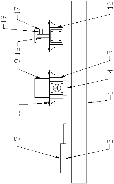
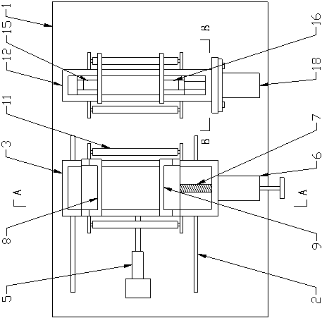
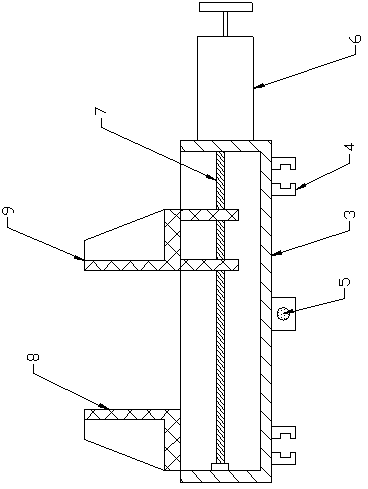
[0018] Such as Figure 1-4 As shown, a tightening device for a cylindrical material cutting machine includes a base 1, a track 2 is provided along the length direction on the left side of the base 1, and a moving tightening device is mounted on the track 2, and the moving tightening device The mobile frame 3 is provided with a rectangular parallelepiped groove with an upper opening inside, the two ends of the lower surface of the mobile frame 3 are provided with rail clips 4, and the middle of the lower surface of the mobile frame 3 is connected with electric Adjusting rod 5, the end surface of one end of the moving frame 3 is connected with a rotating motor 6, said rotating motor 6 is connected with an adjusting screw 7, one end of the upper surface of the moving frame 3 is fixedly provided with a positioning seat A8, and the other on the upper surface of the moving frame 3 One end is provided with a positioning seat B9. The lower surface of the positioning seat B9 is provided...

Embodiment 2

[0021] Such as Figure 1-4 As shown, a tightening device for a cylindrical material cutting machine includes a base 1, a track 2 is provided along the length direction on the left side of the base 1, and a moving tightening device is mounted on the track 2, and the moving tightening device The mobile frame 3 is provided with a rectangular parallelepiped groove with an upper opening inside, the two ends of the lower surface of the mobile frame 3 are provided with rail clips 4, and the middle of the lower surface of the mobile frame 3 is connected with electric Adjusting rod 5, the end surface of one end of the moving frame 3 is connected with a rotating motor 6, said rotating motor 6 is connected with an adjusting screw 7, one end of the upper surface of the moving frame 3 is fixedly provided with a positioning seat A8, and the other on the upper surface of the moving frame 3 One end is provided with a positioning seat B9. The lower surface of the positioning seat B9 is provided...


PUM


Abstract

The invention relates to a clamping device of a cylindrical material cutting machine. The clamping device includes a base; a rail is arranged at the left side of the base in the length direction; a mobile clamping device is arranged on the rail; the mobile clamping device includes a mobile frame, a positioning seat A and a positioning seat B; an electric adjustment rod is connected to the center of a lower surface of the mobile frame; an end surface of one end of the mobile frame is connected to a rotation motor; rolling shafts are arranged on the upper part of two side surfaces of the mobile frame; a fixed clamping device is arranged at the right side of the base; the fixed clamping device includes a fixed frame, a cavity is formed in the center of the fixed frame in the length direction, and sliding grooves are formed in two side walls of the cavity; a sliding plate A and a sliding plate B are symmetrically arranged in the sliding grooves, wherein the sliding plate A and the sliding plate B have T-shaped cross section structures; a reinforcement plate is arranged on the side surfaces of the sliding plate A and the sliding plate B; the lower end surface of the sliding plate B is connected to a hydraulic device; and rolling shafts are arranged on two side surfaces of the fixed frame. The clamping device is reliable in fixing, is easy to move, is high in continuous production ability, and is high in safety.

Description

Technical field [0001] The invention belongs to the technical field of hoisting machinery manufacturing, in particular to a cutting device, in particular to a tightening device of a cylindrical material cutting machine. Background technique [0002] With the development of society, there are more and more applications of hoisting machinery, and the refined production of hoisting machinery will follow. In the production and processing of cranes, the crane travel wheels are usually rolled with round steel. At this time, it is necessary to cut the round steel into sections and then process it. At present, in the production of mechanical processing, the cutting of cylindrical alloy parts mainly uses clamps to press and fix them, and the cutting is performed manually. This way there is a fixed cylindrical material. Unreliable, difficult to move, inconvenient for continuous operation, low cutting efficiency, and high potential safety hazards. Summary of the invention [0003] The purpo...

Claims


Application Information

Patent Timeline
Patent Type & Authority Patents(China)
IPC IPC(8): B23Q3/06
CPCB23Q3/062
Inventor 任海涛
Owner HENAN MINE CRANE
Learn More