
Retracting mechanism of slicing machine

A technology of retraction mechanism and slicer, which is applied in the direction of metal processing, etc., can solve the problems of destroying samples, easily reducing the service life of blades, and prone to sticking knives, etc., to achieve the effect of preventing sticking knives and protecting samples and blades

Active Publication Date: 2016-12-21
浙江省金华市科迪仪器设备有限公司
View PDF5 Cites 6 Cited by
  • Summary
  • Abstract
  • Description
  • Claims
  • Application Information

AI Technical Summary

Problems solved by technology

[0004] but figure 1 When the microtome is working, the sample fixing mechanism cannot be retracted after one cut. During the upward movement of the sample fixing mechanism with the moving seat 2, the blade will contact the sample, which is prone to sticking to the knife, which not only damages the sample, but also easily Reduced blade life

Method used


Image

  • Retracting mechanism of slicing machine
  • Retracting mechanism of slicing machine
  • Retracting mechanism of slicing machine

Examples


Embodiment Construction

[0033] The present invention will be described in detail below in conjunction with the drawings.

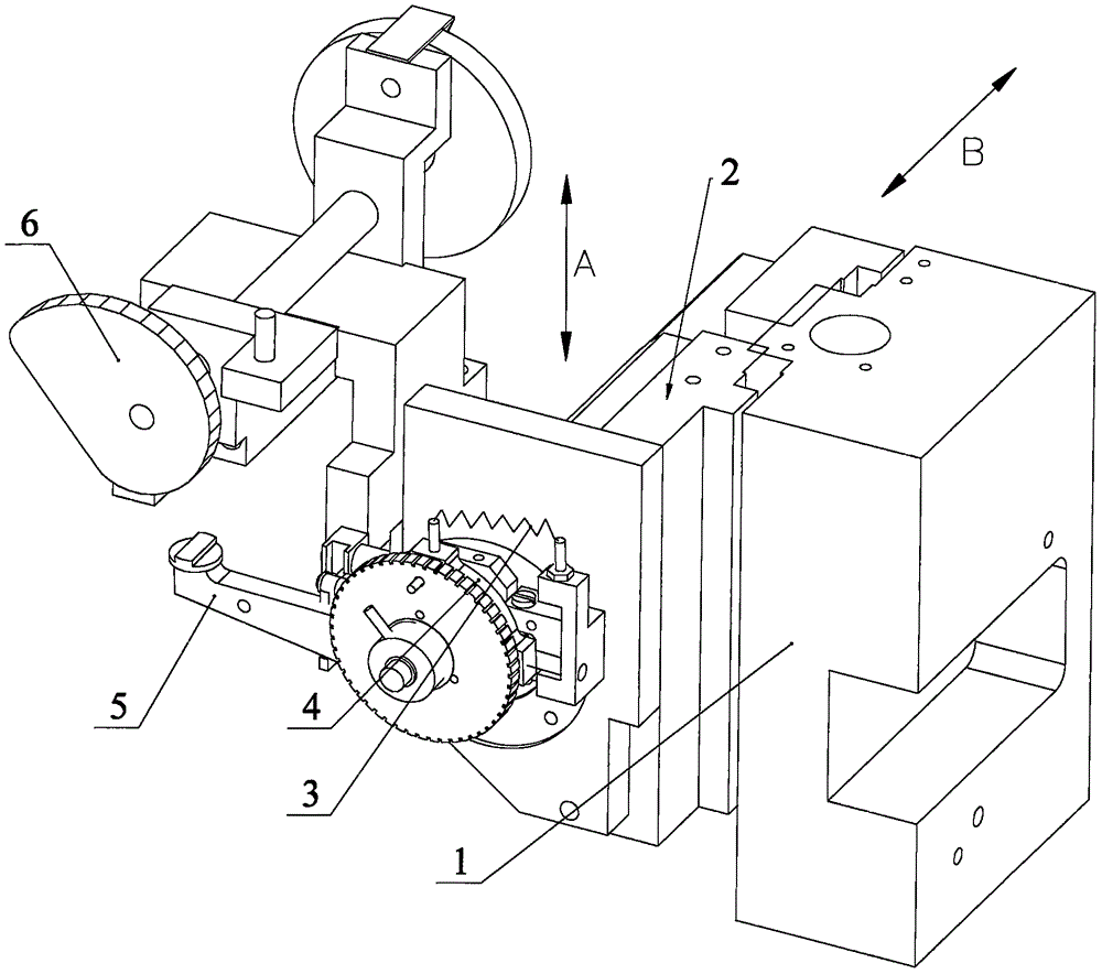
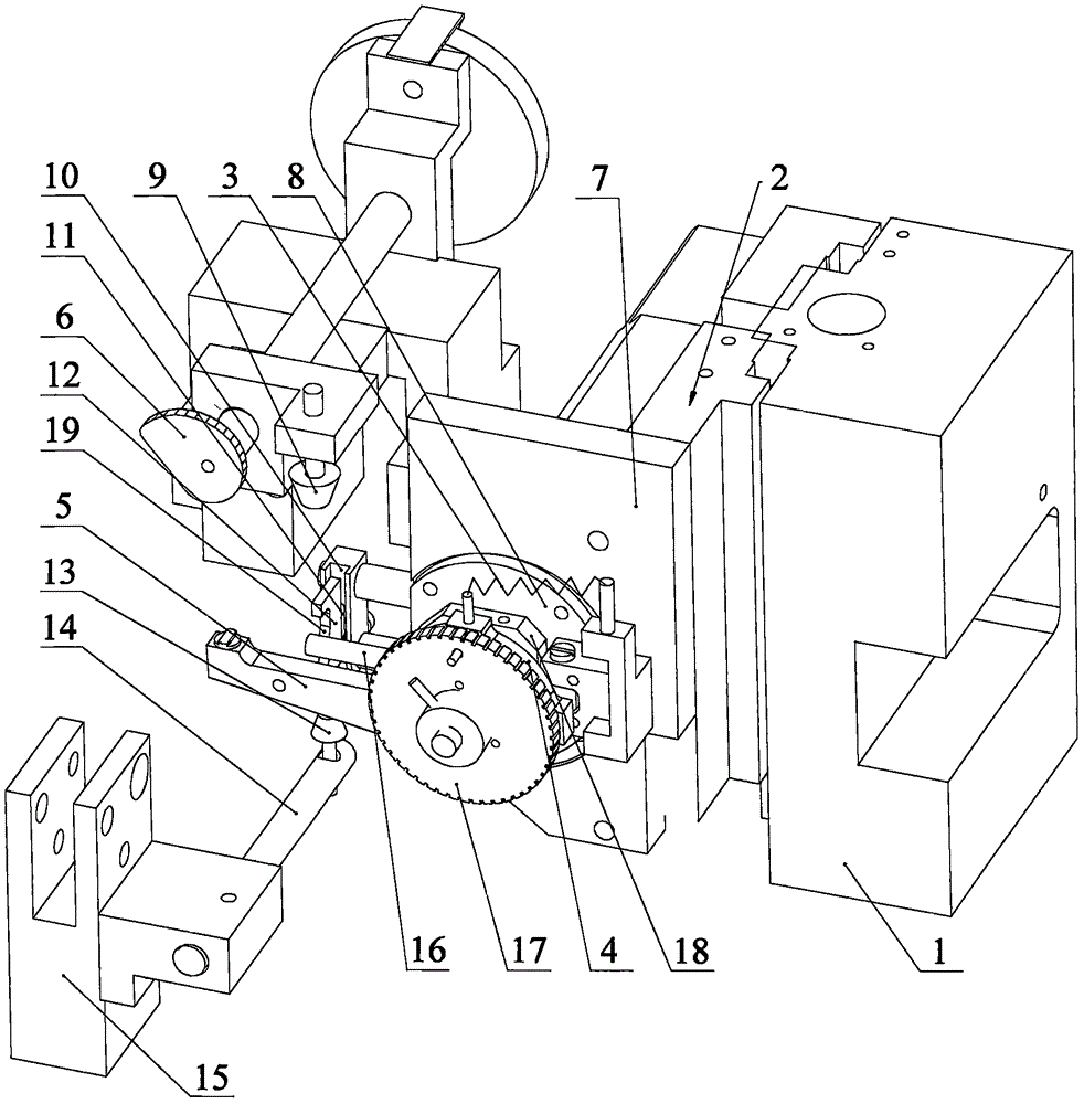
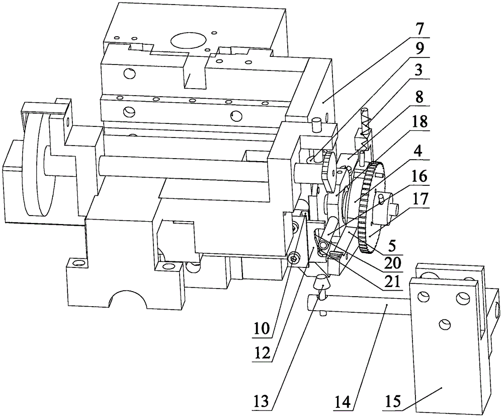
[0034] Such as figure 2 , 3 As shown in and 4, a slicing machine with a retracting mechanism. The slicing machine includes the structure described in the background art, which includes a base 1, a movable base 2, a return spring 3, a one-way bearing 4, a protrusion 5, and an advance To the eccentric disk 6, the movable seat 2 is slidably arranged on the machine seat 1, and the sample sending mechanism is installed on the movable seat 2. The sample sending mechanism includes a one-way bearing 4, and the inner ring of the one-way bearing 4 is connected with a screw rod 23, The moving base 2 includes a mounting plate 7 with a through hole for the screw rod to pass through. The screw rod has a limit ring 26. The one-way bearing 4 and the limit ring 26 are respectively located on both sides of the through hole. The retracting mechanism includes :

[0035] The elastic member 25 is sleeved...


PUM


Abstract

The invention discloses a retracting mechanism of a slicing machine. The retracting mechanism comprises an elastic piece, a retracting control block, a fixed disk, a sliding limiting piece, an upper jacking block and a lower jacking block; the elastic piece is located between a mounting plate and a limiting ring; the retracting control block is externally sleeved on a lead screw; one side of the retracting control block is hinged to the mounting plate; the fixed disk is fixed relative to the lead screw; the sliding limiting piece is provided with a groove matched with a control rod of the retracting control block; the depth of the upper part of the groove is greater than that of the lower part of the groove; the upper jacking block is used to allow the control rod to be located at the upper part of the groove; and the lower jacking block is used to allow the control rod to be located at the lower part of the groove, and drives the retracting control block to rotate. According to the retracting mechanism, after a movable seat moves down to the lowest point, the lead screw can be retracted, blade sticking is prevented, and a sample and a blade can be protected effectively.

Description

Technical field [0001] The invention relates to a biological tissue slicer, in particular to a retracting mechanism of the slicer. Background technique [0002] In the middle of the last century, with the continuous recognition and research of diseases, in addition to the diagnosis of diseases from gross tissues through the naked eye, it is also necessary to diagnose diseases from tissue structure and cell changes. This requires biological tissues to be made into thin slices of about 5um. Observed under a microscope, a microtome for biological tissues is produced. The biological tissues are set on the embedding frame by paraffin, and then the embedding frame is installed on the chuck of the embedding frame, and sliced ​​by a blade. [0003] Such as figure 1 Shown is a schematic diagram of an existing slicer. The moving base 2 is slidably arranged on the base 1. The moving base 2 can be controlled to reciprocate in the direction A on the base 1 through a hand wheel or electric mecha...

Claims


Application Information

Patent Timeline
Patent Type & Authority Applications(China)
IPC IPC(8): B26D1/06B26D7/06B26D5/22
CPCB26D1/06B26D5/22B26D7/0608
Inventor 江泽群董志荣
Owner 浙江省金华市科迪仪器设备有限公司
Features
  • Generate Ideas
  • Intellectual Property
  • Life Sciences
  • Materials
  • Tech Scout
  • Unparalleled Data Quality
  • Higher Quality Content
  • 60% Fewer Hallucinations
Learn More