Screw discharge device
A technology of discharging device and screw, applied in the field of screw discharging device, can solve the problems of poor mixing effect and other problems
- Summary
- Abstract
- Description
- Claims
- Application Information
AI Technical Summary
Problems solved by technology
Method used
Image

Examples
Embodiment 1
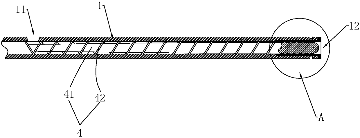
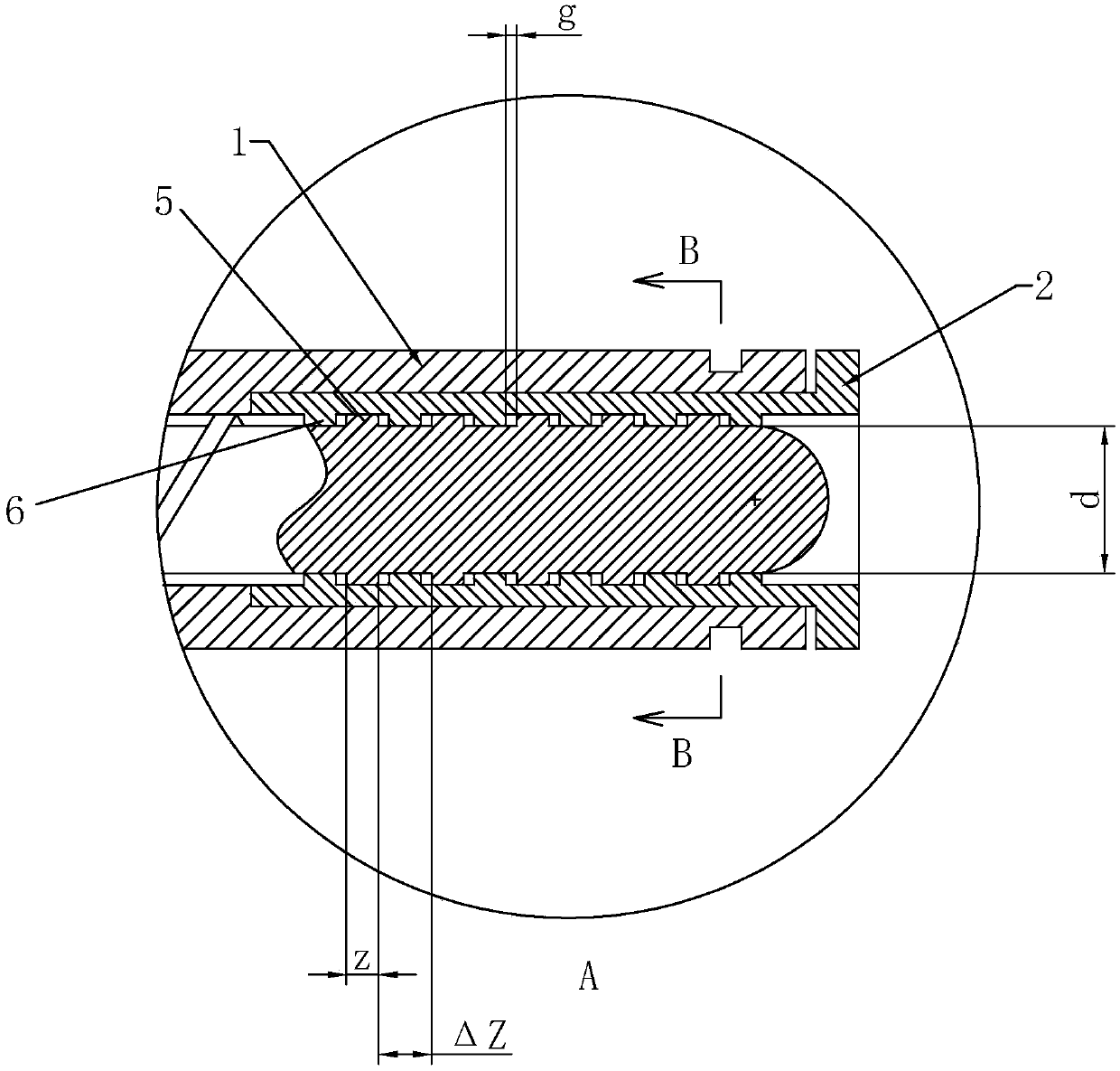
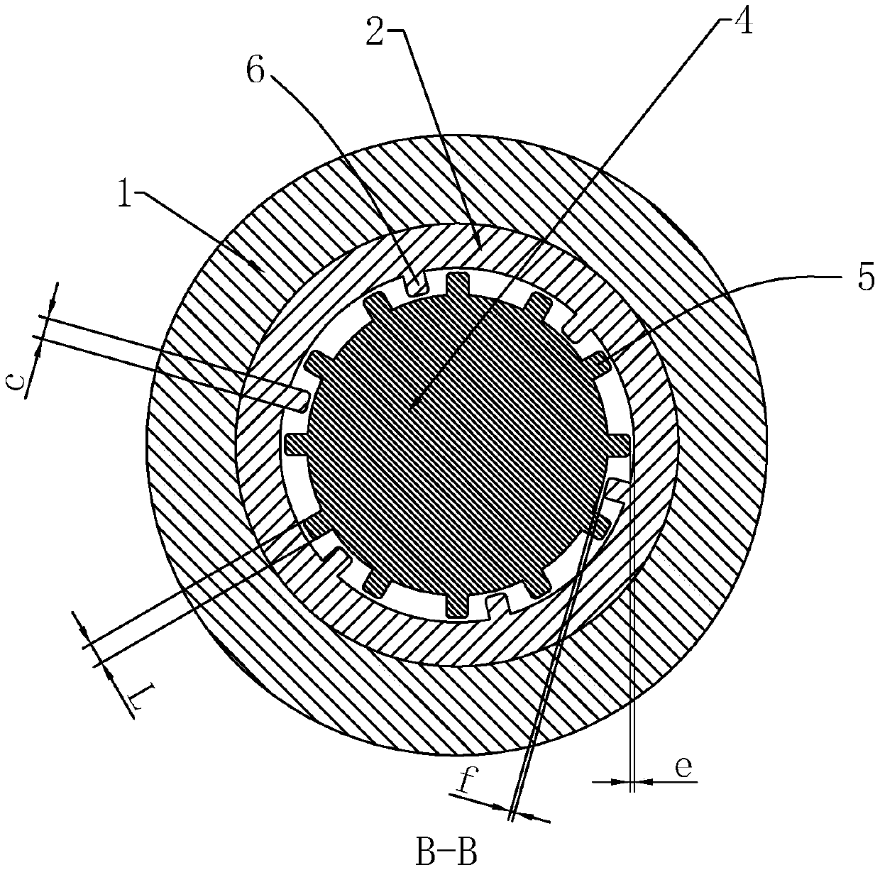
[0023] Embodiment 1: A screw discharge device, including a sleeve 1, a feed port 11 is opened on the side wall of one end of the sleeve 1, and the other end of the sleeve 1 is a discharge port 12, and the sleeve 1 is located at the side of the discharge port 12 One end is fixedly installed with a stirring sleeve 2, the stirring sleeve 2 extends into the sleeve 1 and the inner diameter of the stirring sleeve 2 is in interference fit with the sleeve 1, and the inner tooth group is arranged 6 times along the axial direction of the stirring sleeve 2, and each ring of the inner tooth group consists of Composed of 6 internal teeth 6 arranged at even intervals, the length a of the internal teeth 6 along the axial direction is 15 mm, the distance b between two adjacent internal teeth 6 along the axial direction is 25 mm, and the width c of the internal teeth 6 = 11 mm . The screw rod 4 is arranged in the sleeve 1 and can rotate relative to the sleeve 1. The screw rod 4 is composed of ...
Embodiment 2
[0024] Embodiment 2: A screw discharge device, including a sleeve 1, a feed port 11 is opened on the side wall of one end of the sleeve 1, and the other end of the sleeve 1 is a discharge port 12, and the sleeve 1 is located at the side of the discharge port 12 One end is fixedly installed with a stirring sleeve 2, the stirring sleeve 2 extends into the sleeve 1 and the inner diameter of the stirring sleeve 2 is in interference fit with the sleeve 1, and the inner tooth group is arranged 6 times along the axial direction of the stirring sleeve 2, and each ring of the inner tooth group consists of Composed of 12 internal teeth 6 arranged at even intervals, the length a of the internal teeth 6 along the axial direction is 15 mm, the distance b between two adjacent internal teeth 6 along the axial direction is 25 mm, and the width c of the internal teeth 6 = 11 mm . The screw rod 4 is arranged in the sleeve 1 and can rotate relative to the sleeve 1. The screw rod 4 is composed of...
Embodiment 3
[0025] Embodiment 3: A screw discharge device, including a sleeve 1, a feed port 11 is opened on the side wall of one end of the sleeve 1, and the other end of the sleeve 1 is a discharge port 12, and the sleeve 1 is located at the side of the discharge port 12 One end is fixedly installed with a stirring sleeve 2, the stirring sleeve 2 extends into the sleeve 1 and the inner diameter of the stirring sleeve 2 is in interference fit with the sleeve 1, and the inner tooth group is arranged 6 times along the axial direction of the stirring sleeve 2, and each ring of the inner tooth group consists of Composed of 12 internal teeth 6 arranged at even intervals, the length a of the internal teeth 6 along the axial direction is 15 mm, the distance b between two adjacent internal teeth 6 along the axial direction is 25 mm, and the width c of the internal teeth 6 = 11 mm . The screw rod 4 is arranged in the sleeve 1 and can rotate relative to the sleeve 1. The screw rod 4 is composed of...
PUM
 Abstract
Description
Claims
Application Information
 - R&D
- Intellectual Property
- Life Sciences
- Materials
- Tech Scout
- Unparalleled Data Quality
- Higher Quality Content
- 60% Fewer Hallucinations
Browse by: Latest US Patents, China's latest patents, Technical Efficacy Thesaurus, Application Domain, Technology Topic, Popular Technical Reports.
© 2025 PatSnap. All rights reserved.Legal|Privacy policy|Modern Slavery Act Transparency Statement|Sitemap|About US| Contact US: help@patsnap.com