Sewing machine bobbin thread residue detection device

A detection device and sewing machine technology, applied in sewing machine control devices, bobbin winding in sewing machines, sewing machine components, etc., can solve the problems of defective high-end fabrics, failure to stop and alarm in time, etc., to ensure sewing quality and ensure sewing. The effect of efficiency

Inactive Publication Date: 2016-12-21
JACK SEWING MASCH CO LTD
View PDF7 Cites 9 Cited by
  • Summary
  • Abstract
  • Description
  • Claims
  • Application Information

AI Technical Summary

Problems solved by technology

However, this method has two disadvantages: one, after the bobbin is out of thread, if the sewing machine is stepped on empty, the bobbin will rotate due to the vibration of the machine, so the above-mentioned method has the defect of being unable to stop the alarm in time; two, if t

Method used


Image

  • Sewing machine bobbin thread residue detection device
  • Sewing machine bobbin thread residue detection device
  • Sewing machine bobbin thread residue detection device

Examples


Embodiment 1

[0039] Embodiment 1: The winding counting device of this embodiment is a switch counting device.

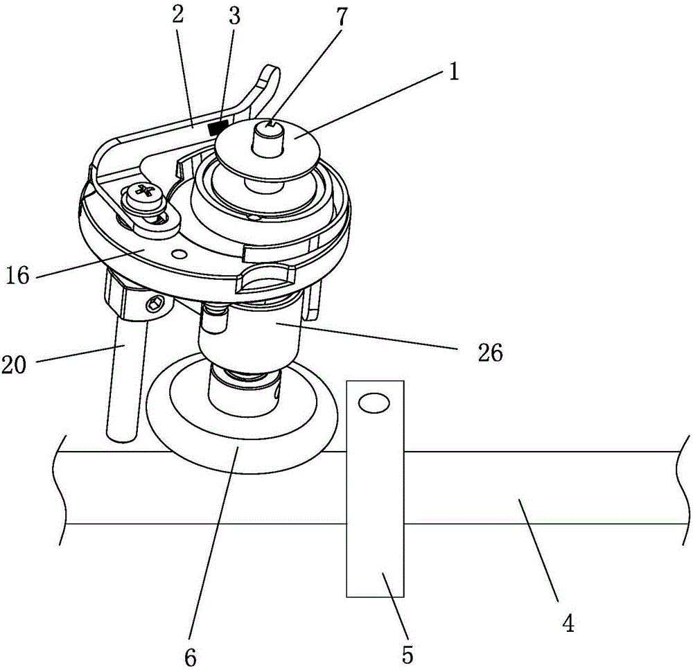
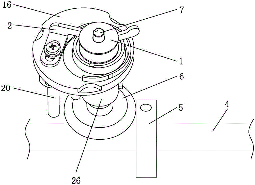
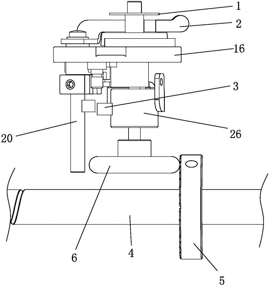
[0040] The switch counting device comprises a pressure sensor 3 or a switch arranged on the wire pressing control board 2 of the wire winder or on the connecting rod 26 of the wire winder.

[0041] Such as figure 1 As shown, it is the state diagram of the lockstitch sewing machine when the winder is not working. Bobbin 1 is sleeved on the bobbin shaft 7 of bobbin winder. At this moment, the winding driving wheel 5 is not in contact with the winding wheel 6, and the thread pressing control plate 2 is not in contact with the bobbin 1. At this time, the pressure sensor 3 is not connected or the switch is not connected. Such as figure 2As shown, it is the state diagram of the winder when it is working. At this moment, the winding driving wheel 5 contacts the winding wheel 6, the pressure sensor 3 contacts the bobbin 1, the pressure sensor 3 on the pressure control plate 2 is to...

Embodiment 2

[0051] Embodiment 2: The difference between this embodiment and Embodiment 1 is that the winding counting device adopts a Hall induction counting device.

[0052] The Hall induction counting device includes a side surface of the winding liner 14 (such as image 3 shown) or the upper surface (such as Figure 4 Shown) or the magnet one 15 of lower surface and the hall sensor one 17 that is arranged on the winding device main seat 16. Wherein, the Hall sensor one 17 is arranged on the main seat 16 of the winding device through the sensor bracket 18 .

[0053] When the winder on the top of the sewing machine head is working, the working state is as follows: image 3 , 4 As shown, the bobbin 1 is placed above the winding liner 14, and the thread pressing control panel 2 is pulled in the direction of the bobbin 1, and now the bobbin 1 starts to wind. When winding, the winding liner 14 is relatively fixed to the bobbin 1, that is, the number of turns of the winding liner 14 and t...

Embodiment 3

[0054] Embodiment 3: The difference between this embodiment and Embodiment 1 is that the winding counting device adopts another Hall induction counting device.

[0055] Such as Figure 5 As shown, when the bobbin winder is winding, since the winding wheel 6 and the bobbin 1 are also relatively fixed, that is, the number of turns of the winding wheel 6 and the bobbin 1 is consistent. Therefore, present embodiment is provided with magnet 2 19 on the winding wheel 6, is provided with support 21 on the winding camshaft 20 of winding device, and one end of support 21 is sleeved on the winding camshaft 20 and is fixed by screw, and another One end is positioned above the reel 6 . Hall sensor 2 22 is arranged on the bracket 21 above the reel 6 . When winding, the winding wheel 6 rotates, and the magnet 2 19 approaches the Hall sensor 22 once every time, that is, every time the winding wheel 6 turns around, the Hall sensor 22 counts up by one until the winding is completed, and the ...


PUM


Abstract

The invention belongs to the technical field of sewing machines and in particular relates to a sewing machine bobbin thread residue detection device. The device comprises a winding counting device and a bobbin thread counting device, wherein the winding counting device is used for monitoring the number of laps of winding of a bobbin; the bobbin thread counting device is used for monitoring the number of laps of unwinding of bobbin threads when the bobbin is used for sewing; a controller can acquire the number of laps of winding of the winding counting device and the number of laps of unwinding of the bobbin thread counting device and achieve the function of bobbin thread residue detection by monitoring the number of laps of winding and the number of laps of unwinding. The sewing machine bobbin thread residue detection device has the advantages that as the two devices are arranged to monitor the number of laps of winding and the number of laps of unwinding respectively and the preset value of the bobbin thread residue of the controller is adjustable and can be set according to the requirements of users, warning can be achieved more accurately, early warning can be achieved and warning needs not be carried out until all the bobbin threads are used up, thus preventing defective products or reworks of high-end fabrics due to float stitching caused because the bobbin threads are lacked and ensuring the sewing efficiency and quality.

Description

Technical field: [0001] The invention belongs to the technical field of sewing machines, in particular to a detection device for the bottom thread margin of a sewing machine. Background technique: [0002] The working principle of the lockstitch sewing machine is roughly: the hook and the needle cooperate to interweave the upper thread and the bottom thread in the form of a thread loop and a thread loop to form a lock stitch. The upper thread is generally longer, its length is between 3000-4000m, and the upper thread position is on the platen, which is easy to observe. But the bottom line is generally short, its length is between 20-50m, and the bobbin position is under the bottom plate, wrapped by the hook and the bobbin case, it is difficult to observe the margin of the bottom line. Therefore, when the bottom thread wound on the bobbin is almost used up, the worker cannot observe the amount of thread on the bottom thread. If the sewing action is continued, empty stepping ...

Claims


Application Information

Patent Timeline
IPC IPC(8): D05B59/02D05B59/00D05B69/36
CPCD05B59/02D05B59/00D05B69/36D05D2205/12D05D2205/32
Inventor 马鸣岚潘建国黄明学
Owner JACK SEWING MASCH CO LTD
Why Eureka
Try Eureka