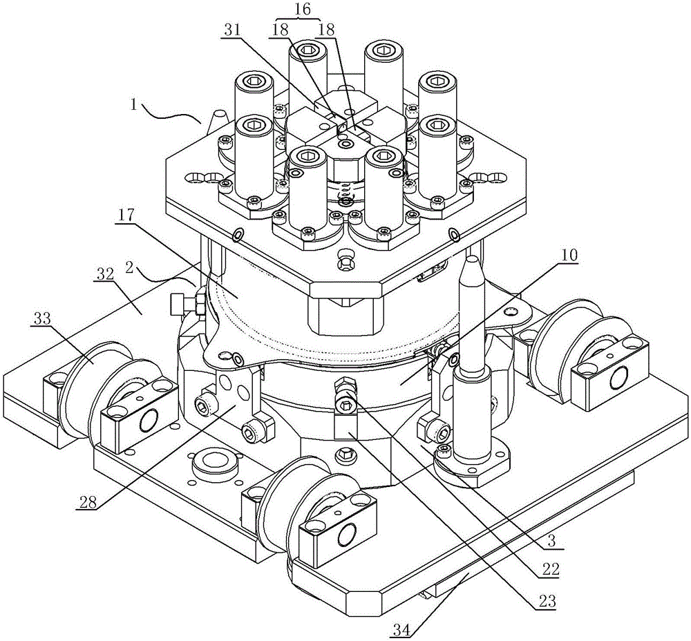
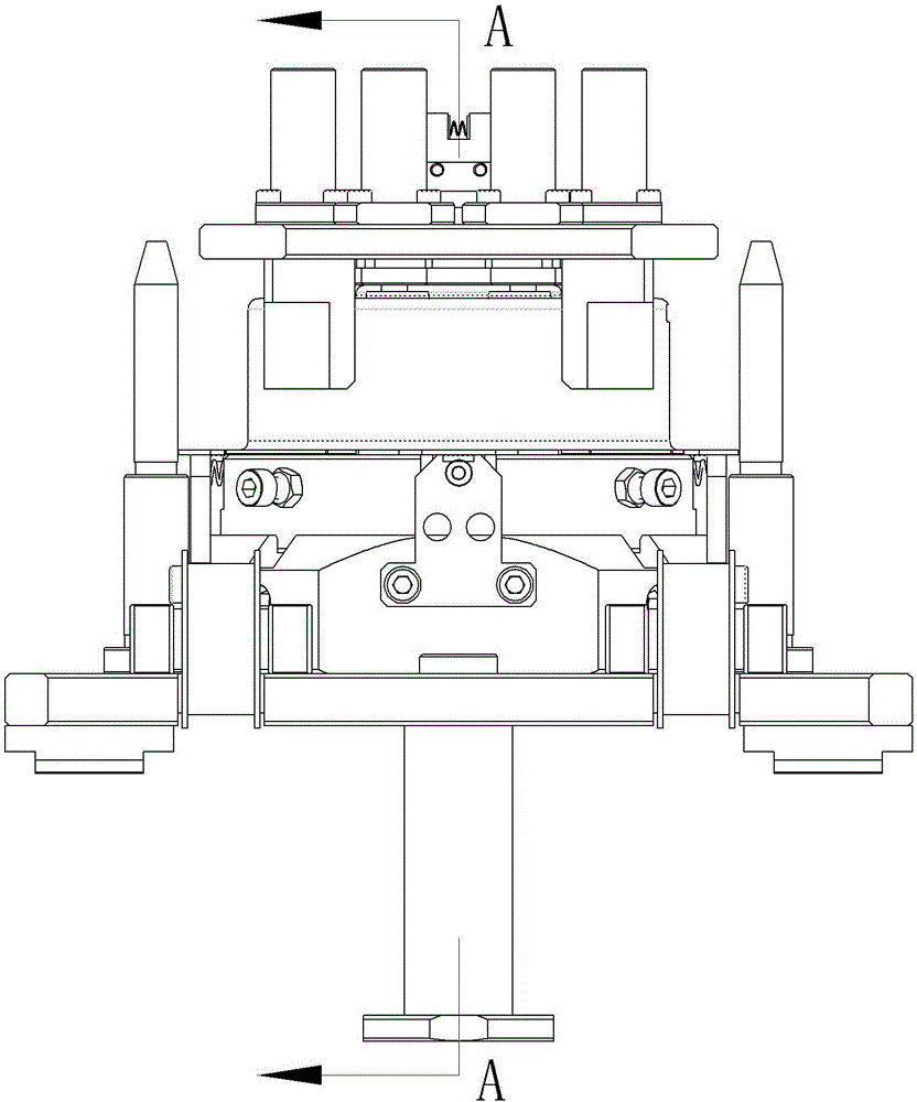
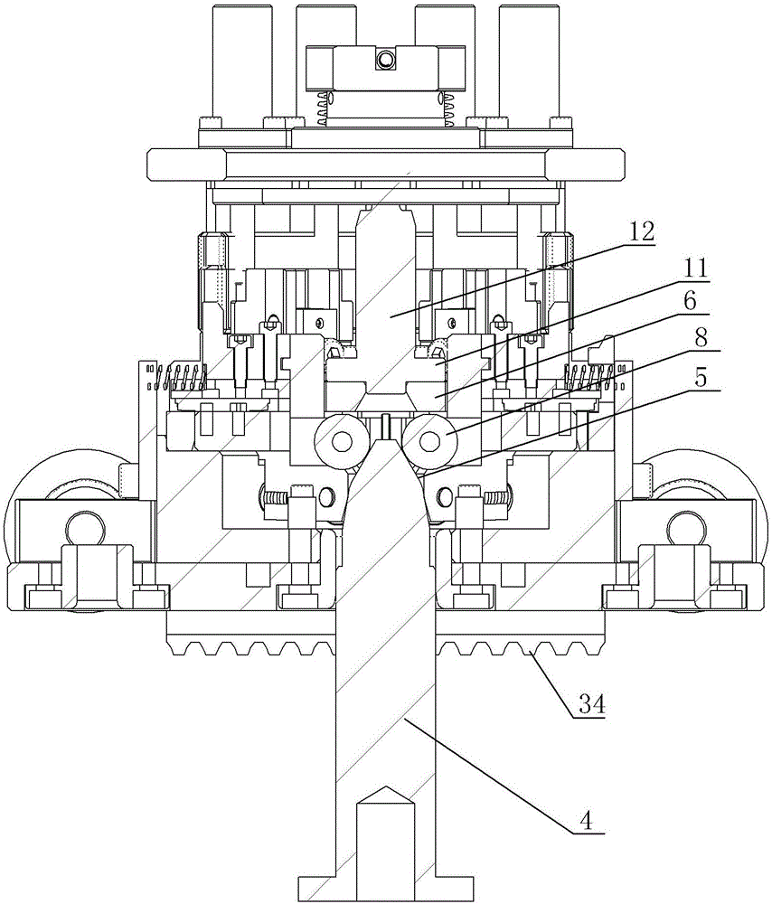
[0022] A fixture structure suitable for magnetic tile assembly, see figure 1 : It includes an upper jig 1, a lower jig 2. The lower jig 2 includes a base 3, an upper positioning structure, and a central positioning shaft 4. The central positioning shaft 4 protrudes from the base 3, and the upper part of the central positioning shaft 4 is closed upward The arc transition structure 5, the upper positioning structure includes several arc-shaped magnetic tile positioning blocks 6, the magnetic tile positioning blocks 6 combine to form a circular structure, and the adjacent magnetic tile positioning blocks 6 are provided with magnetic tile positioning spacers 7. The bottom inner end of each magnetic tile positioning block 6 is provided with a first guide wheel 8, and the inner end of each first guide wheel 8 is close to the outer end surface of the arc transition structure 5 of the central positioning shaft 4. The outer side of the bottom of the tile positioning block 6 is closely attached to one end of the first guide spring 9 at the corresponding position, the other end of the first guide spring 9 is closely attached to the inner end surface of the upper ring wall 10 of the base 3, and the center of the magnetic tile positioning block 6 A central pressing block 11 is provided at the end. The bottom end surface of the central pressing block 11 is pressed against the upper end surface inside the bottom of the magnetic tile positioning block 6. The upper part of the central pressing block 11 is provided with an upper convex structure 12, and the top of the upper convex structure 12 is provided There is a positioning cone structure 13, and the upper jig 2 includes a pressing end surface 14, a pressing side portion 15, and a center jaw structure 16. The pressing end surface 14 is used to press the top of the casing 17, and the pressing side 15 is used Pressing the outer ring surface of the casing 17, the central claw structure 16 includes two claws 18, the upper part of the claw 18 is connected to the inner wall of the upper jig 1 through the rotating shaft 19, a drive spring 20 is arranged between the claws 18, and two The lower end structure 21 of the claw 18 is used for clamping and positioning the cone structure 13.
[0023] A guide post 22 is fixedly mounted on the outer side of the middle and upper part of each magnet tile positioning block 6, the upper ring wall 10 of the base 3 is provided with a vertical guide groove 23 at a position corresponding to the guide post 22, and the outer end of the guide post 22 is clamped in In the corresponding vertical guide groove 23;
[0024] The magnetic tile positioning spacer 7 includes a convex positioning spacer 24 and a bottom support block 25. The inner end of the bottom support block 25 is embedded in the middle outer part of the magnetic tile positioning block 6, and the middle inner side of each magnetic tile positioning block 6 A second guide wheel 26 is provided. The inner end of each second guide wheel 26 presses the upper outer end surface of the arc transition structure 5 of the central positioning shaft 4, which ensures that the magnetic tile positioning spacer 7 can interact with the magnetic tile positioning block. 6 synchronous action;
[0025] The outer end of the bottom support block 25 is provided with a second guide spring 27, the base 3 is provided with an upper stop block 28 corresponding to the outer end of the second guide spring 27, and the outer end of the second guide spring 27 is top-mounted on the corresponding position. Stop 28;
[0026] A first guide spring hole 29 is provided on the outer side of the bottom of the magnetic shoe positioning block 6 corresponding to the inner end of the first guide spring 9. The inner end of the first guide spring 9 is located in the first guide spring hole 29. A wear-resistant head 30 is installed at the outer end, and the outer end of the wear-resistant head 30 is close to the inner end surface of the upper ring wall 10 of the base;
[0027] The upper jig 1 is provided with an escape groove 31 on the outside of the drive spring 20 corresponding to the two jaws 18 of the central jaw structure 16, so that the outer hook can drive the lower end structure 21 of the two jaws 18 into the escape groove 31. Open action
[0028] The base 3 is fixedly mounted on the support base 32, the support base 32 is provided with a downwardly convex guide wheel 33, and the bottom of the support base 32 is provided with a guide tooth structure 34 corresponding to the position of the timing belt, which ensures the smooth operation of the entire structure on the production line delivery.
[0029] After adopting the above technical solution, when the upper jig 1 is pressed down to the casing 17, the two claws 18 on the upper jig 1 are opened and then closed under the action of the positioning cone structure 13, so that the upper jig 1 is pressed down When the central claw structure 16 clamps the positioning cone structure 13 on the lower jig 2, at the same time the central pressing block 11 presses down to drive the bottom of the magnetic tile positioning block 6 to press down, because each magnetic tile positioning block 6 The inner end of the bottom is provided with a first guide wheel 8, and each magnetic tile positioning block 6 is provided with a second guide wheel 26 inside the middle part, which makes the first guide wheel 8 and the second guide wheel 26 follow the arc transition structure 5 The lower part expands outward, which drives all the magnetic tile positioning blocks 6 and the magnetic tile positioning spacers 7 to simultaneously expand outward, making each magnetic tile close to the adhesive part of the inner wall of the casing 17, when the upper jig 1 separates from the lower jig At the time of tool 2, under the action of the first guide spring 9 and the second guide spring 27, the lower jig is reset, so that the magnet tile and casing can be separated from the lower jig, which allows the magnet tile and casing to be carried out on the production line Automatic assembly, the entire assembly process is quick and convenient, ensuring the efficient and accurate production of the entire production line, and the quality of the products produced.
[0030] The specific embodiments of the present invention have been described in detail above, but the content is only the preferred embodiments created by the present invention and cannot be considered as limiting the scope of implementation of the present invention. All equal changes and improvements made in accordance with the scope of application of the invention should still fall within the scope of this patent.