
A conveying line arrangement structure of an automatic assembly line for an automobile motor rotor

A motor rotor and conveying line technology, applied in the field of conveying line arrangement structure, can solve the problems of poor uniformity of incoming materials for product parts, inability to realize automatic production, irregularity and other problems

Active Publication Date: 2019-10-25
SUZHOU LING AUTOMATION EQUIP
View PDF5 Cites 0 Cited by
  • Summary
  • Abstract
  • Description
  • Claims
  • Application Information

AI Technical Summary

Problems solved by technology

[0002] The automotive motor industry has always been a labor-intensive industry. Due to the particularity of the products, it has been unable to realize automatic production. Due to the poor uniformity and irregularity of the incoming materials of the product components, a large amount of labor is required in the production and assembly process to locate the production product and identify the direction. , leading to low production capacity, backward production technology and low pass rate of finished products
At the same time, with the current huge labor cost and the expansion of labor gap and other factors, the cost of automobile motor production and assembly has risen sharply. After the domestic automobile motor rotor puts the iron core and winding into the rotating shell, the iron core and winding are manually completed The welding of the rotating shell, and then manually transported to the shaping station for shaping, and then manually rounding the central axis of the rotating shell and pressing the bearings require a lot of manpower to equip, resulting in a large amount of labor costs. Realize automatic production, high production capacity, high yield rate of automatic equipment to support

Method used


Image

  • A conveying line arrangement structure of an automatic assembly line for an automobile motor rotor
  • A conveying line arrangement structure of an automatic assembly line for an automobile motor rotor
  • A conveying line arrangement structure of an automatic assembly line for an automobile motor rotor

Examples


Embodiment Construction

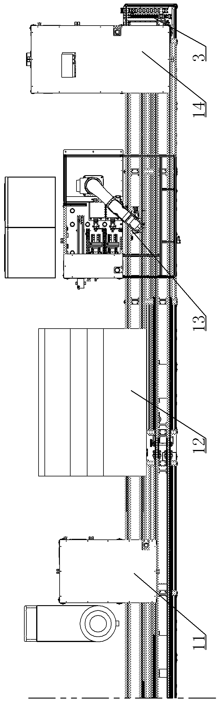
[0016] A conveying line arrangement structure of an automatic assembly line for automobile motor rotors, see Figure 1 to Figure 4 : It includes a frame 1, two parallel linear tracks are arranged on the frame 1, and the two ends of the two parallel linear tracks are respectively provided with a front end transition structure 2 and a rear end transition structure 3, and one of the linear tracks is for conveying The product conveying line 4 of the product, and the other straight line is the return line 5 that conveys the tray back to the beginning of the production line. The product conveying line 4 is arranged with a feeding station 6, a welding station 7, and a shaft along the product conveying direction. Press-in station 8, copper wire shaping station 9, turning station 10, cleaning station 11, dynamic balance test station 12, characteristic inspection station 13, rear bearing press-in station 14, product conveying line 4 each The positions of each station are respectively pr...


PUM


Abstract

The invention provides a conveying line configuration structure of an automatic assembling line for an automobile motor rotor. By adoption of the conveying line configuration structure, the mechanical manufacturing of the motor rotor can be completed on a production line, so that efficient and accurate production of the overall production line can be ensured; and in addition, the produced motor rotor has a good quality. The conveying line configuration structure comprises a rack, wherein two parallel linear tracks are formed in the rack; a front end transitional structure and a back end transitional structure are arranged at the two ends of each of the two parallel linear tracks respectively; one linear track is a production conveying line for conveying products while the other linear track is a material returning line for conveying trays back to the starting end of the production line; the product conveying line is provided with a material inlet station, a fusion welding station, an axial pressing-in station, a copper line shaping station, a turning station, a cleaning station, a dynamic balance testing station, a characteristic inspection station, and a back bearing pressing-in station in the product conveying direction; and a vertical direction air cylinder lifting mechanism and a blocking structure are arranged in each station of the product conveying line separately.

Description

technical field [0001] The invention relates to the technical field of motor assembly, in particular to a conveying line layout structure of an automatic assembly line for motor rotors of automobiles. Background technique [0002] The automotive motor industry has always been a labor-intensive industry. Due to the particularity of the products, it has been unable to realize automatic production. Due to the poor uniformity and irregularity of the incoming materials of the product components, a large amount of labor is required in the production and assembly process to locate the production product and identify the direction. , leading to low production capacity, backward production technology and low pass rate of finished products. At the same time, with the current huge labor cost and the expansion of labor gap and other factors, the cost of automobile motor production and assembly has risen sharply. After the domestic automobile motor rotor puts the iron core and winding in...

Claims


Application Information

Patent Timeline
Patent Type & Authority Patents(China)
IPC IPC(8): H02K15/02
CPCH02K15/02
Inventor 付叶磊
Owner SUZHOU LING AUTOMATION EQUIP
Features
  • Generate Ideas
  • Intellectual Property
  • Life Sciences
  • Materials
  • Tech Scout
  • Unparalleled Data Quality
  • Higher Quality Content
  • 60% Fewer Hallucinations
Learn More