
A conveyor line structure suitable for magnetic tile assembly

A technology of conveying lines and magnetic tiles, which is applied in the direction of electromechanical devices, electrical components, manufacturing stator/rotor bodies, etc., and can solve the problems of poor uniformity of incoming materials for product parts, inability to realize automatic production, irregularities, etc.

Active Publication Date: 2019-01-11
SUZHOU LING AUTOMATION EQUIP
View PDF3 Cites 0 Cited by
  • Summary
  • Abstract
  • Description
  • Claims
  • Application Information

AI Technical Summary

Problems solved by technology

[0002] The automotive motor industry has always been a labor-intensive industry. Due to the particularity of the products, it has been unable to realize automatic production. Due to the poor uniformity and irregularity of the incoming materials of the product components, a large amount of labor is required in the production and assembly process to locate the production product and identify the direction. , leading to low production capacity, backward production technology and low pass rate of finished products
At the same time, with the current huge labor cost and the expansion of the labor gap and other factors, the cost of automobile motor production and assembly has risen sharply. The assembly of domestic automobile porcelain and magnetic tiles needs to set up casing feeding stations, magnetic tile feeding stations, casings, etc. Glue application area, magnetic tile and casing attachment station, and then set up the curing production line. Pressing fixtures need to be set up on the curing production line, and the detection structure is set behind the curing production line, and the bearing riveting station is set behind the detection structure , the entire magnetic tile installation needs to be operated by multiple workers at multiple stations, which requires a lot of manpower to equip, resulting in a large amount of labor costs, and there is an urgent need for automation equipment that can realize automated production, high productivity, and high yield rate to match

Method used


Image

  • A conveyor line structure suitable for magnetic tile assembly

Examples


Embodiment Construction

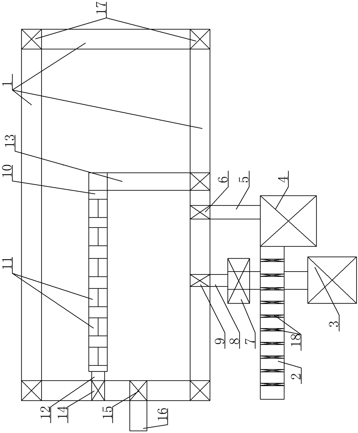
[0012] A conveyor line structure suitable for magnetic tile assembly, see figure 1 : It includes a circular and closed jig curing production line 1, one side of the jig curing production line 1 is provided with an organic casing feeding line 2, and the outer side of the casing feeding line 2 is provided with a magnetic tile distributor 3, and the curing A lower jig (not shown in the figure) is installed on the track corresponding to the solidification production line 1, an organic shell coating machine 4 is arranged behind the shell feeding line 2, and the output end of the shell coating machine 4 is set There is a first conveying manipulator 5. The first conveying manipulator 5 puts the coated casing onto the lower jig at the corresponding position of the jig curing production line 1. This position is the casing assembly and loading station 6, and the magnetic The output end of tile splitting machine 3 is provided with magnetic tile assembly mold 7, and magnetic tile assembly...


PUM


Abstract

The invention provides a conveying line structure for assembly of magnetic tiles. The conveying line structure is characterized in that a magnetic tile and a machine casing are automatically assembled, so as to ensure the high-efficiency and precise production of the whole production line, and high quality of a produced product. The conveying line structure comprises a jig curing production line, wherein the jig curing production line is circulated and sealed; a machine casing charging line is arranged at one side of the jig curing production line, and a magnetic tile distributing machine is arranged at the outer side of the machine casing charging line; a lower jig is arranged on a rail corresponding to the jig curing production line; a machine casing coating machine is arranged behind the machine casing charging line; a first conveying manipulator is arranged at the output end of the machine casing coating machine, and is used for putting the coated machine casing onto the lower jig on the corresponding position of the jig curing production line, and the position is a machine casing assembly charging working position; a magnetic tile assembly die is arranged at the output end of the magnetic tile distributing machine.

Description

technical field [0001] The invention relates to the technical field of motor assembly, in particular to a conveyor line structure suitable for magnetic tile assembly. Background technique [0002] The automotive motor industry has always been a labor-intensive industry. Due to the particularity of the products, it has been unable to realize automatic production. Due to the poor uniformity and irregularity of the incoming materials of the product components, a large amount of labor is required in the production and assembly process to locate the production product and identify the direction. , leading to low production capacity, backward production technology and low pass rate of finished products. At the same time, with the current huge labor cost and the expansion of the labor gap and other factors, the cost of automobile motor production and assembly has risen sharply. The assembly of domestic automobile porcelain and magnetic tiles needs to set up casing feeding stations,...

Claims


Application Information

Patent Timeline
Patent Type & Authority Patents(China)
IPC IPC(8): H02K15/03
CPCH02K15/03
Inventor 王红红
Owner SUZHOU LING AUTOMATION EQUIP
Features
  • Generate Ideas
  • Intellectual Property
  • Life Sciences
  • Materials
  • Tech Scout
  • Unparalleled Data Quality
  • Higher Quality Content
  • 60% Fewer Hallucinations
Learn More